background image

(E)

 (1)

Safety Precautions

Sony Manufacturing Systems Corporation products are designed in full consideration of
safety. However, improper handling during operation or installation is dangerous and may
lead to fire, electric shock or other accidents resulting in serious injury or death. In addition,
these actions may also worsen machine performance.
Therefore, be sure to observe the following safety precautions in order to prevent these
types of accidents, and to read these “Safety Precautions” before operating, installing, main-
taining, inspecting, repairing or otherwise working on this unit.

Warning Indication Meanings

The following indications are used throughout this manual, and their contents should be
understood before reading the text.

 Warning

Failure to observe these precautions may lead to fire, electric shock or other accidents re-
sulting in serious injury or death.

 Caution

Failure to observe these precautions may lead to electric shock or other accidents resulting
in injury or damage to surrounding objects.

n

This indicates precautions which should be observed to ensure proper handling of the equip-
ment.

 Warning

Do not use this unit with voltages other than the specified supply voltage as this may
result in fire or electric shock.

Do not perform installation work with wet hands as this may result in electric shock.

Do not disassemble or modify the unit as this may result in injury or damage the
internal circuits.

 Caution

Be sure to check the machine and device conditions to ensure work safety before
working on the machine.

Be sure to cut off the power supply, air and other sources of drive power before
working on the machine. Failure to do so may result in fire or accidents.

When turning on the power supply, etc. to operate the machine, take care not to
catch your fingers in peripheral machines and devices.

Summary of Contents for PL101 Series

Page 1: ...後は 後日お役に立つこともございますので 必ず保管してください Read all the instructions in the manual carefully before use and strictly follow them Keep the manual for future references Lesen Sie die ganze Anleitung vor dem Betrieb aufmerksam durch und folgen Sie beim Betrieb des Geräts den Anweisungen Bewahren Sie diese Bedienungsanleitung zum späferen Nachlesen griffbereit auf ...

Page 2: ...ent of electromagnetic disturbance characteristics of industrial scientific and medical ISM radio frequency equipment EN 50 082 2 95 Electromagnetic compatibility Generic immunity standard Part 2 Industrial environment 警告 本装置を機械指令 EN 60 204 1 の適合を受ける機器にご使用の場合は その規 格に適合するように方策を講じてから ご使用ください Warning When using this device with equipment governed by Machine Directives EN 60 204 1 measures should be t...

Page 3: ...をしています 表示内容をよく理解してから 本文をお読みください 警告 この表示の注意事項を守らないと 火災や感電などにより死亡や大ケガなど人身 事故につながることがあります 注意 この表示の注意事項を守らないと 感電やその他事故によりケガをしたり周辺の 物品に損害を与えることがあります 注意 機器の正しい取扱のために 注意していただきたい事項です 警告 表示された電源電圧以外での電圧で使用しないでください 火災や感電の 原因となる恐れがあります 濡れた手での取付作業はおやめください 感電の原因となります 本体を分解や改造したりしないでください ケガの恐れや 内部回路が破 損することがあります 注意 作業を行う前には 機械や装置の状況をよく確かめて作業の安全を確保し てください 電源やエアーなどの駆動源は必ず切って作業をしてください 火災や事故 の原因となります 電源などを入れて動かす場合は...

Page 4: ...用はお やめください ヘッド部は除く 一般的な注意事項 以下は当社製品を正しくお使いいただくための一般的注意事項です 個々の詳細 な取扱上の注意は 本取扱説明書に記述された諸事項および注意をうながしてい る説明事項に従ってください 始業または操作時には 当社製品の機能および性能が正常に作動していることを 確認してからご使用ください 当社製品が万一故障した場合 各種の損害を防止するための充分な保全対策を施 してご使用ください 仕様に示された規格以外での使用または改造を施された製品については 機能お よび性能の保証は出来ませんのでご留意ください 当社製品を他の機器と組合わせてご使用になる場合は 使用条件 環境などによ り その機能および性能が満足されない場合がありますので 充分ご検討の上ご 使用ください ...

Page 5: ...PL101 J i 目次 1 概要 1 1 1 はじめに 1 1 2 主な特長 1 1 3 注意事項 1 1 4 システム構成 2 2 取付方法 3 2 1 取付寸法図 3 2 2 準備 4 2 3 取付 4 3 主な仕様 5 3 1 仕様 5 3 2 コネクタ 6 3 3 付属品 6 3 4 オプション 6 ...

Page 6: ...PL101 ii J ...

Page 7: ...変動にも強く 高精度が得られます 最小分解能は 1 umです MJ600 MJ620と組合せた場合 IP67です PL101 RH 原点内蔵です PL101 R RH 1 3 注意事項 強力な磁気を発生させるものは この製品の近くに設置しないでください ス ケール精度が損なわれることがあります この製品は 周囲温度範囲 0dC 45dC 以内で 直射日光や熱源を避けてご使 用ください 大電力リレー 高電圧 大電流開閉器などのノイズ発生源から 0 5 m以上離し てご使用ください ヘッドケーブルおよび出力ケーブルは 動力ラインとは別配線してください 本機に結合して使用されるリレー ソレノイド モーターなどには ノイズ防 止策をしてください 延長ケーブルは 充分な耐久性を持った物ですが 耐久性は ご使用になる条 件により左右されますので ケーブルに無理な応力のかからないような処置を お願いいた...

Page 8: ...PL101 2 J 1 4 システム構成 スケール部 ヘッド部 インターポレータ部 出力 接続図 800 um 10 5 2 1 um 1 Vp p MJ500 600 620 PL101 N R RH SL700 Series アナログ パルス スケール ヘッド PL101 ヘッドケーブル コネクタ 延長ケーブル インターポレータ ...

Page 9: ... 12 65 12 200以下 有効長 ケーブル長 300 PL101 N R PL101 RH ケーブル長 3000 全長 有効長 40 20 9 ロール 0 2d オフセット 0 2 0 05 M マシンガイド 48 1 5 43 5 ピッチ 0 1d センターマーク 2 x 2 M3深さ5 11 5 20 PL101 ヘッド Ø D穴 平行ピン挿入用 原点マーク 原点位置 ヨー 0 2d 0 04 4 Ø 4 4 クリアランス 0 35 0 1 6 6 65 21 M 25 0 16 M 0 08 M ...

Page 10: ...する長さ は 4 5 mm としてください 2 3 取付 1 スケールとヘッドのSONYマークの向きを同じにします 2 ヘッドには信号検出位置の目安となるセンターマークが刻印されています センターマークが常に有効長内にあるように設定します 3 センターマークがスケールの原点マークの中心に合う位置で原点を設定しま す 4 ヘッドの検出面とスケールとの間に付属のスペーサを挟み込み M3のネジを 用いてヘッドを取付け固定します 締付トルクは0 6 0 8 N mとしてください 5 ヘッド取付後 スペーサを抜き取ります 6 スケールとヘッドの相対位置を確認します 下図参照 ヨー 0 2d クリアランス 0 35 0 1 オフセット 0 2 ロール 0 2d ピッチ 0 1d M3 スケール ヘッド PL101 センターマーク スペーサ ...

Page 11: ...2 10 um 精度 10 um SL700シリーズとの組合せによる 製造出荷時 20 Cにおける1 m当りの精度 クリアランス 0 35 0 1 mm オフセット 0 2 mm 姿勢 ピッチ 0 1d 変化 ヨー 0 2d ロール 0 2d 出力信号 1 Vp p アナログ出力 差動出力 クリアランス 0 35 mmのとき 電源電圧 DC 5 V 5 消費電力 Max 0 8 W 最大応答速度 6 4 m s MJ600 620との組合せによる 1 um分解能時 ケーブル長 300 mm 3000 mm 製品質量 60 g 150 g 使用温度範囲 0 45dC 保存温度範囲 _20 50dC 外形寸法図参照 約0 5 Vp p 約0 6 Vp p 800 um 約800 um SIN COS _SIN _COS _Z Z ...

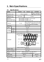
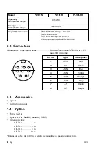
Page 12: ...ss A ICES 003 CLASS A DIGITAL DEVICE 1 3 4 5 8 7 6 2 3 2 コネクタ メーカー名 型名 ホシデン製 TCP6180 01 1120 ミニDIN8ピンプラグ ピンNo 信号 ケーブル色相 1 VCC 赤 2 0 V 白 3 SIN 青 4 _SIN 黄 5 COS 橙 6 _COS 灰 7 _Z 緑 8 Z 紫 3 3 付属品 スペーサ 取扱説明書 3 4 オプション ワイパー SZ16 取付確認用スペーサセット SZ17 延長ケーブル CK T12 1 m CK T13 3 m CK T14 5 m CK T15 10 m 接続可能な延長ケーブルは10 mまでです ...

Page 13: ...ock or other accidents re sulting in serious injury or death Caution Failure to observe these precautions may lead to electric shock or other accidents resulting in injury or damage to surrounding objects n This indicates precautions which should be observed to ensure proper handling of the equip ment Warning Do not use this unit with voltages other than the specified supply voltage as this may re...

Page 14: ...owing general precautions along with those given specifically in this manual to ensure proper use of the products Before and during operations be sure to check that our products function properly Provide adequate safety measures to prevent damages in case our products should de velop malfunctions Use outside indicated specifications or purposes and modification of our products will void any warran...

Page 15: ...Main Features 1 1 3 Usage Notes 1 1 4 System Configuration 2 2 Installation Procedure 3 2 1 Installation Dimensional Diagram 3 2 2 Preparation 4 2 3 Installation 4 3 Main Specifications 5 3 1 Specifications 5 3 2 Connectors 6 3 3 Accessories 6 3 4 Option 6 ...

Page 16: ...PL101 ii E ...

Page 17: ... PL101 RH Built in reference point PL101 R RH 1 3 Usage Notes Do not place objects that generate strong magnetic fields in the vicinity of this product This could harm the accuracy of the scale This product should be used within an ambient temperature range of 0 to 45 C and should not be exposed to direct sunlight or heat sources During operation be sure to keep the unit 0 5 m or more away from la...

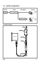
Page 18: ... 2 1 um 1 Vp p MJ500 600 620 PL101 N R RH SL700 Series Analog signal Pulse signal Scale Head PL101 Head scale Connector Extension cable interpolator 1 4 System Configuration Scale Head Interpolator Output Connection Diagram ...

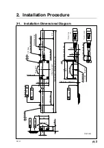
Page 19: ...5 48 1 5 43 5 11 5 20 PL101 Head Reference mark Origin position 0 04 4 Ø 4 4 6 6 65 21 M 25 0 16 M 0 08 M 200 or less Effective length Cable length 300 Cable length 3000 Total length Effective length 40 Roll 0 2d Offset 0 2 M Machine guide Pitch 0 1d Center mark 2 x 2 M3 Depth 5 Ø D hole for inserting parallel pin Yaw 0 2d Clearance 0 35 0 1 ...

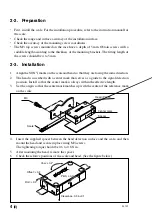
Page 20: ...that they are facing the same direction 2 The head is inscribed with a center mark that serves as a guide to the signal detection position Install so that the center mark is always within the effective length 3 Set the origin so that the center mark matches up with the center of the reference mark on the scale 4 Insert the supplied spacer between the head detection surface and the scale and then m...

Page 21: ...acy 10 um When combined with the SL700 series Accuracy per 1 m measured at 20dC at the time of manufacturing and shipping Clearance 0 35 0 1 mm Offset 0 2 mm Change Pitch 0 1d in attitude Yaw 0 2d Roll 0 2d Out signal Supply voltage DC 5 V 5 Power consumption Max 0 8 W Maximum response 6 4 m s With a resolution of 1 um when used in speed combination with an MJ600 620 Cable length 300 mm 3000 mm Pr...

Page 22: ...E 3 2 Connectors Manufacturer name model name Hosiden Corporation TCP6180 01 1120 mini DIN8 pin plug Pin no Signal Cable phase 1 VCC Red 2 0V White 3 SIN Blue 4 _SIN Yellow 5 COS Orange 6 _COS Gray 7 _Z Green 8 Z Purple 3 3 Accessories Spacer Instruction manual 3 4 Option Wiper SZ16 Spacer set for checking mounting SZ17 Extension cable CK T12 1 m CK T13 3 m CK T14 5 m CK T15 10 m Extension cables ...

Page 23: ...ndbuchs werden Sie auf die folgenden Hinweise und Symbole stoßen Machen Sie sich mit ihrer Bedeutung vertraut bevor Sie den Text lesen Warnung Eine Mißachtung dieser Hinweise kann zu Feuer elektrischen Schlägen oder anderen Unfällen führen die schwere Verletzungen oder Tod zur Folge haben können Vorsicht Eine Mißachtung dieser Hinweise kann zu elektrischen Schlägen oder anderen Unfällen führen die...

Page 24: ...st daher kann es nicht an solch einen Ort verwenden an dem es Erschütterung ausgesetzt ist Ausschließlich des Lesekopfaufbaus Allgemeine Vorsichtsmaßnahmen Beachten Sie bei der Verwendung von Sony Manufacturing Systems Corporation Produkten die folgenden allgemeinen sowie die in dieser Bedienungsanleitung besonders hervorgehobenen Vorsichtsmaßnahmen um eine sachgerechte Behandlung der Produkte zu ...

Page 25: ...Hauptmerkmale 1 1 3 Benutzungshinweise 1 1 4 Systemkonfiguration 2 2 Installationsverfahren 3 2 1 Installations Maßzeichnung 3 2 2 Vorbereitung 4 2 3 Montage 4 3 Hauptspezifikationen 5 3 1 Technische Daten 5 3 2 Steckverbinder 6 3 3 Zubehör 6 3 4 Sonderzubehör 6 ...

Page 26: ...PL101 ii G ...

Page 27: ...eferenzpunkt PL101 R RH 1 3 Benutzungshinweise Bringen Sie keine Gegenstände die starke Magnetfelder erzeugen in die Nähe dieses Produkts Dadurch könnte die Genauigkeit des Maßstabs beeinträchtigt werden Dieses Produkt sollte innerhalb eines Umgebungstemperaturbereichs von 0 bis 45 dC verwendet und keinem direkten Sonnenlicht oder Wärmequellen ausgesetzt werden Achten Sie darauf daß die Einheit wä...

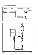
Page 28: ...kabel Interpolator Kopf PL101 Kopfmaßstab Stecker Maßstab 1 4 Systemkonfiguration Maßstab Kopf Interpolator Ausgabe Anschlussdiagramm 10 5 2 1 µm Serie SL700 PL101 N R RH 800 µm 1 Vs s MJ500 600 620 Analogsignal Impulssignal ...

Page 29: ...3 5 11 5 20 PL101 Lesekopf Referenzpunktmarkierung Nullpunktposition 0 04 4 Ø 4 4 6 6 65 21 M 25 0 16 M 0 08 M M Maschinenführungsbahn Versatz 0 2 Gieren 0 2d Ø D Loch für Parallelstift Effektive Länge Gesamtlänge Effektive Länge 40 Abstand 0 35 0 1 200 oder weniger Stergung 0 1d Kabellänge 300 Kabellänge 3000 Mittenmarke 2 x 2 M3 Tiefe 5 Rollen 0 2d ...

Page 30: ...ng weisen 2 Der Kopf ist mit einer Mittenmarke versehen die als Anhaltspunkt für die Signalerkennungsposition dient Den Kopf so montieren dass die Mittenmarke immer innerhalb der effektiven Länge liegt 3 Stellen Sie den Nullpunkt so ein dass die Mittenmarke mit der Mitte der Referenz punktmarkierung auf dem Maßstab übereinstimmt 4 Den mitgelieferten Abstandshalter zwischen Kopfabtastfläche und Maß...

Page 31: ...t 10 um Bei Einsatz mit Serie SL700 Die Genauigkeit pro 1 m wurde bei der Herstellung und vor dem Versand bei 20dC gemessen Abstand 0 35 0 1 mm Versatz 0 2 mm Lageänderung Steigung 0 1d Gieren 0 2d Rollen 0 2d Ausgangssignal 1 Vs s Analogausgang Differentialausgang Versorgungsspannung DC 5V 5 Leistungsaufnahme Max 0 8 mA Maximale Ansprechges 6 4 m s Bei einer Auflöung von 1 um bei Einsatz in chwin...

Page 32: ...SE A 3 2 Steckverbinder Hersteller Modellbezeichnung Hosiden Corporation TCP6180 01 1120 8 poliger Mini DIN Stecker Stift Nr Signal Kabelphase 1 VCC Rot 2 0 V Weiß 3 SIN Blau 4 _SIN Gelb 5 COS Orange 6 _COS Grau 7 _Z Grün 8 Z Violett 3 3 Zubehör Abstandshalter Bedienungsanleitung 3 4 Sonderzubehör Wischer SZ16 Abstandshaltersatz zur Montageprüfung SZ17 Verlängerungskabel CK T12 1 m CK T13 3 m CK T...

Page 33: ...PL101 ...

Page 34: ...ystems Corporation et sont destinées exclusivement à l usage des acquéreurs de l équipement décrit dans ce manuel Sony Manufacturing Systems Corporation interdit formellement la copie de quelque partie que ce soit de ce manuel ou son emploi pour tout autre but que des opérations ou entretiens de l équipement à moins d une permission écrite de Sony Manufacturing Systems Corporation Die in dieser An...

Page 35: ...もの とし それ以外についての保証はいたしかねます 2 保証期間内でも 次の場合は有償修理となります 1 火災 地震 水害 落雷およびその他天災地変によ る故障 2 使用上の誤りおよび不当な修理や改造による故障 3 消耗品および付属品の交換 4 本書の提示が無い場合 5 本書にお買い上げ日 お客様名 販売店名等の記入 が無い場合 ただし 納品書や工事完了報告書が ある場合には その限りではありません 3 離島 遠隔地への出張修理および持込修理品の出張修理 については 出張に要する実費を別途申し受けます 4 本書は日本国内においてのみ有効です 5 本書の再発行はいたしませんので 紛失しないよう大切 に保管してください 本書はお買上げ日から保証期間中に故障が発生した場 合には 右記保証規定内容により無償修理を行うこと をお約束するものです PL101 ...

Page 36: ...ny Manufacturing Systems Corporation PL101 2 913 130 04 このマニュアルは再生紙を使用しています ソニーマニュファクチュアリングシステムズ株式会社 346 0035 埼玉県久喜市清久町1 10 Sony Manufacturing Systems Corporation 1 10 Kiyoku cho Kuki shi Saitama 346 0035 Japan http www sonysms co jp ...

Reviews: