13
GB
Location and Function of Parts
m
Ceiling bracket mounting screw
holes
When you install the Camera Unit to the
ceiling or on a shelf, etc. in a high
position, secure the supplied ceiling
bracket to these holes using the supplied
four screws. The four feet are attached to
the holes at the factory.
For installation, see “Installing the
Camera Unit in a High Position” on page
17.
n
Tripod screw holes (1/4-20UNC)
When you install the camera to a tripod,
secure the tripod to these holes.
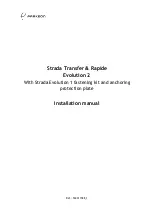
o
BOTTOM switches
Used for the output signal format
selection and RS-232C/RS-422
selection.
For details, see “Setting of the
BOTTOM switches”.
Setting of the BOTTOM switches
Switch 1 (59.94i/50i signal format
selector)
Set to ON for output of 50i high-definition
signal format, or OFF for output of 59.94i
signal format.
For normal use, you need not switch the
setting.
Switch 2 (RS-232C/RS-422 selector)
Set to ON for RS-422, or OFF for RS-232C.
Switches other than Switch 1 and 2 are
inactive with this Camera Unit and are set to
OFF at the factory. Do not use these
switches, although they do not affect the
Camera Unit if they are set to ON.
Bottom
qf
qd
qg
Note
O
N
1
2
3
4
O
N
1
2
3
4
Switch 2
Switch 1
Summary of Contents for PCSA-CHG90
Page 25: ...25JP 設置する 9 付属のネジ 3M3 8 3 本でシーリングブラケット A と B を固定する 10カメラ後面の端子にケーブルを接続する 天井 3M3 8 付属 天井 ...
Page 32: ...JP 32 設置する 8 付属のネジ 3M3 8 3 本でシーリングブラケット A と B を固定する 3M3 8 付属 ...
Page 41: ...41JP 仕様 カメラユニット PCSA CHG90 寸法図 正面 267 208 2 5 9 0 側面 上面 底面 三脚ネジ 単位 mm ...
Page 45: ......
Page 87: ...43GB Specifications ...