
235
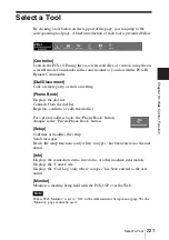
Location and Function of Parts and Controls
A
ppe
nd
ix
Location and
Function of Parts
and Controls
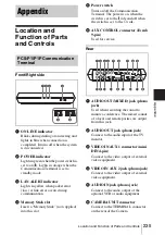
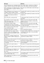
Front/Right side
a
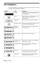
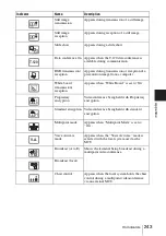
ON LINE indicator
Blinks during dialing or answering and
lights in blue when connection is
completed. It turns off when the system
is disconnected.
b
POWER indicator
Lights in green when the power switch is
set to on (
@
). Lights in orange when the
Communication Terminal is set to
standby mode.
c
LAN ALERT indicator
Lights in yellow when packet error
(loss) or link error occurs during
communication.
d
Memory Stick slot
Insert a “Memory Stick” (not supplied)
into this slot.
e
Power switch
Turns on/off the Communication
Terminal. The power is on when the
switch is set to the
@
side and off when
the switch is set to the
a
side.
f
AUX CONTROL connector (D-sub
9-pin)
Used for service.
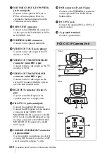
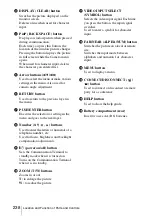
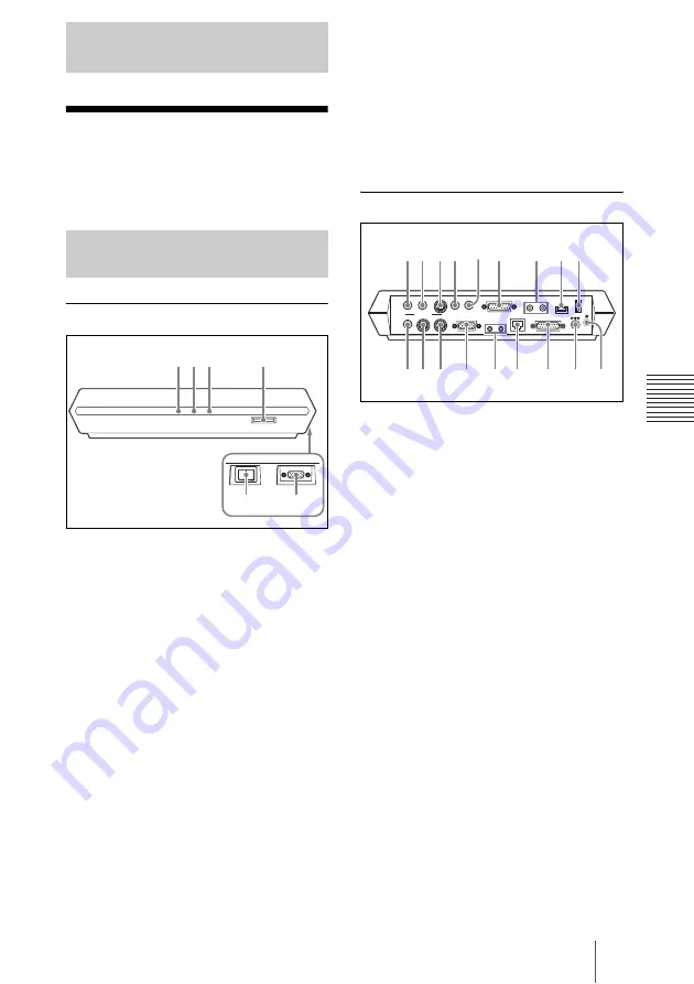
Rear
a
AUDIO OUT (MIXED) jack (phono
jack)
Used when recording the sound to
minute a conference. The mixed sounds
of a local and remote parties are output
from this jack.
b
AUDIO OUT jack (phono jack)
Connect to the audio input of the TV
monitor.
c
VIDEO IN AUX 1 connector (mini
DIN 4-pin)
Connect to the video output of external
video equipment.
d
VIDEO IN AUX 2 jack (phono jack)
Connect to the video output of external
video equipment.
e
AUDIO IN jack (phono jack)
Connect to the audio output of the
optional VCR or audio equipment.
f
CAMERA UNIT connector
Connect to the TERMINAL connector
on the rear of the Camera.
Appendix
PCS-P1/P1P Communication
Terminal
ON LINE
POWER
LAN ALERT
1 2 3
4
5
6
DC 19.5V
AUDIO OUT
AUDIO IN
AUX1–
VIDEO IN–AUX2
CAMERA UNIT
MIC
(PLUG IN POWER)
ISDN UNIT
WHITE
BOARD
(MIXED)
AUX
MAIN– MONITOR– SUB
VIDEO OUT
RGB OUT
DSB
IR OUT
100BASE-TX
10BASE-T
1
2
1
2
1
q; qa qs
qd
qf
qg
qh
qj
qk
2 3
6
7
8 9
5
4
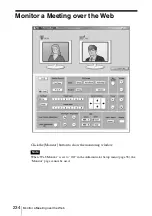
Summary of Contents for PCS-1 - Video Conferencing Kit
Page 284: ...Sony Corporation ...