– 20 –
SECTION 3
DISASSEMBLY
Note :
Follow the disassembly procedure in the numerical order given.
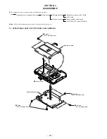
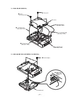
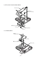
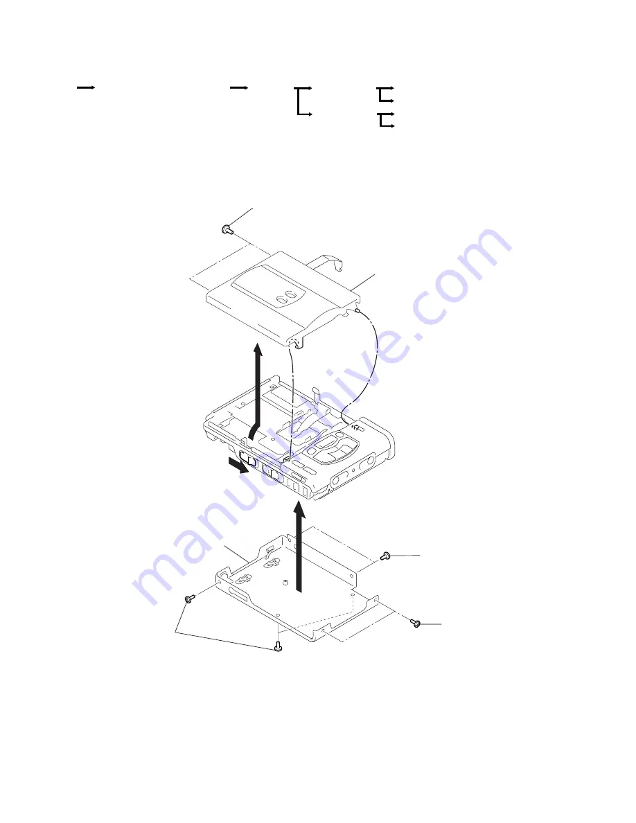
3-1. UPPER PANEL ASSY, BOTTOM PANEL ASSY REMOVAL
r
The equipment can be removed using the following procedure.
Set
Upper panel assy, Bottom panel assy
Main board
Mechanism deck
SWITCH UNIT (with JOG DIAL)
Power board, Switch board
CLV board
Optical pick-up assy, REC board
Battery case assy
7
3
1
Screws
(M1.4 precision pan)
Upper panel assy
2
Knob (Open)
4
Screws
(M1.4 precision pan)
6
Screw
(M1.4 precision pan)
5
Screws
(M1.4 precision pan)
Bottom panel assy
Summary of Contents for MZ-R50 Analog PCLink
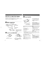
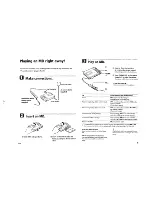
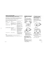
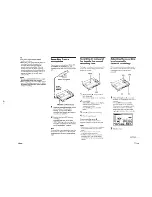
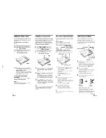
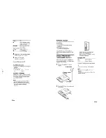
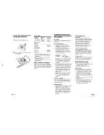
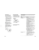
Page 4: ... 4 SECTION 2 GENERAL This section is extracted from instruction manual ...
Page 5: ... 5 ...
Page 6: ... 6 ...
Page 7: ... 7 ...
Page 8: ... 8 ...
Page 9: ... 9 ...
Page 10: ... 10 ...
Page 11: ... 11 ...
Page 12: ... 12 ...
Page 13: ... 13 ...
Page 14: ... 14 ...
Page 15: ... 15 ...
Page 16: ... 16 ...
Page 17: ... 17 ...
Page 18: ... 18 ...
Page 19: ... 19 ...

