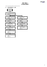


MV-65ST
17
17
2
Back Limiter Level
Procedure:
1. In the “
1
Contrast Level of Luminance Signal” status, press
the
[MENU]
utton to display “Black Limit”, and press the
[RE-
VERSE]
button.
2. Adjust by pressing the
[+]
/
−
buttons so that the
A
value of
waveform (fig. 8-2) becomes 1.0 V
±
0.1 V.
3. Press the
[REVERSE]
button and write the date to EEPROM
(IC402 on the MONITOR board).
3
White Limiter Level
Procedure:
1. In the “
2
Black Limiter Level” status, press the
[MENU]
but-
ton to display “White Limit”, and press the
[REVERSE]
but-
ton.
2. Adjust by pressing the
[+]
/
−
buttons so that the
E
value of
waveform (fig. 8-2) becomes 3.9 V
±
0.1 V.
3. Press the
[REVERSE]
button and write the date to EEPROM
(IC402 on the MONITOR board).
4
R-sub Bright
Procedure:
1. In the “
3
White Limiter Level” status, connect the oscillo-
scope to the TP513 and TP810 on the MONITOR board.
2. Press the
[MENU]
button to display “R-Sub BRT”, and press
the
[REVERSE]
button.
3. Adjust by pressing the
[+]
/
−
buttons so that the
A
value of
waveform (fig. 8-2) becomes 1.0 V
±
0.1 V.
4. Press the
[REVERSE]
button and write the date to EEPROM
(IC402 on the MONITOR board).
5
B-sub Bright
Procedure:
1. In the “
4
R-sub Bright” status, connect the oscilloscope to
the TP513 and TP812 on the MONITOR board.
2. Press the
[MENU]
button to display “B-Sub BRT”, and press
the
[REVERSE]
button.
3. Adjust by pressing the
[+]
/
−
buttons so that the
A
value of
waveform (fig. 8-2) becomes 1.0 V
±
0.1 V.
4. Press the
[REVERSE]
button and write the date to EEPROM
(IC402 on the MONITOR board).
6
R-ch Sub Contrast
Procedure:
1. In the “
5
B-sub Bright” status, connect the oscilloscope to
the TP513 and TP810 on the MONITOR board.
2. Press the
[MENU]
button to display “R-Sub CONT”, and press
the
[REVERSE]
button.
3. Adjust by pressing the
[+]
/
−
buttons so that the
D
value of
waveform (fig. 8-2) becomes 3.4 V
±
0.1 V.
4. Press the
[REVERSE]
button and write the date to EEPROM
(IC402 on the MONITOR board).
7
B-ch Sub Contrast
Procedure:
1. In the “
6
R-ch Sub Contrast” status, connect the oscilloscope
to the TP513 and TP812 on the MONITOR board.
2. Press the
[MENU]
button to display “B-Sub CONT”, and press
the
[REVERSE]
button.
3. Adjust by pressing the
[+]
/
−
buttons so that the
D
value of
waveform (fig. 8-2) becomes 3.4 V
±
0.1 V.
4. Press the
[REVERSE]
button and write the date to EEPROM
(IC402 on the MONITOR board).
8
Gamma 1
Procedure:
1. In the “
7
B-ch Sub Contrast” status, connect the oscilloscope
to the TP513 and TP811 on the MONITOR board.
2. Press the
[MENU]
button to display “Gamma 1”, and press the
[REVERSE]
button.
3. Adjust by pressing the
[+]
/
−
buttons so that the
B
value of
waveform (fig. 8-2) becomes 2.0 V
±
0.1 V.
4. Press the
[REVERSE]
button and write the date to EEPROM
(IC402 on the MONITOR board).
9
Gamma 2
Procedure:
1. In the “
8
Gamma 1” status, press the
[MENU]
button to dis-
play “Gamma 2”, and press the
[REVERSE]
button.
2. Adjust by pressing the
[+]
/
−
buttons so that the
C
value of
waveform (fig. 8-2) becomes 3.2 V
±
0.1 V.
3. Press the
[REVERSE]
button and write the date to EEPROM
(IC402 on the MONITOR board).
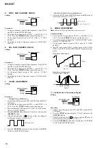
q;
VCO Free Run
Setting:
Procedure:
1. In the “
9
Gamma 2” status, connect a frequency counter to
the TP506 and TP513 on the MONITOR board.
2. Press the
[MENU]
button to display “VCO Free Run”, and press
the
[REVERSE]
button.
3. Adjust by pressing the
[+]
/
−
buttons so that the value of fre-
quency counter becomes 15.734 kHz
±
50 Hz.
4. Confirm that the displayed screen is normally display.
5. Press the
[REVERSE]
button and write the date to EEPROM
(IC402 on the MONITOR board).
qa
Vertical Position
Procedure:
1. In the “
q;
VCO Free Run” status, input the monoscope signal
to the VIDEO INPUT jack (J301 on the POWER board).
2. Press the
[MENU]
button to display “PLL/V Pos”, and press
the
[REVERSE]
button.
3. Adjust by pressing the
[+]
/
−
buttons so that the vertical posi-
tion of screen on the monitor becomes the most suitable.
4. Press the
[REVERSE]
button and write the date to EEPROM
(IC402 on the MONITOR board).
qs
Horizontal Position
Procedure:
1. In the “
qa
Vertical Position” status, press the
[MENU]
button
to display “H Pos”, and press the
[REVERSE]
button.
2. Adjust by pressing the
[+]
/
−
buttons so that the horizontal
position of screen on the monitor becomes the most suitable.
3. Press the
[REVERSE]
button and write the date to EEPROM
(IC402 on the MONITOR board).
+
–
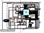
frequency counter
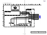
MONITOR board
TP506
TP513
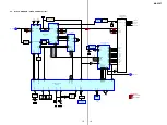
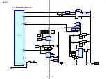
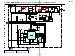
– MONITOR BOARD (SIDE A) –
RV601
RV802
RV803
RV801
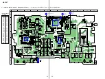
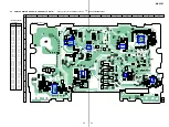
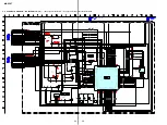
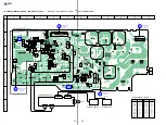
– MONITOR BOARD (SIDE B) –
TP854
TP853
TP952 (+)
TP951 (
−
)
TP802
TP807
TP602
TP601
TP819 TP810
TP506
TP510
TP513
TP405
TP403
TP954
TP953
TP804
TP805
TP812
TP828
TP811
TP808
TP806
Adjustment Location:


