MDX-M690
19
4-4.
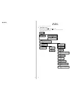
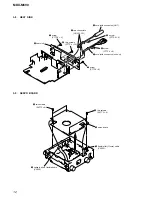
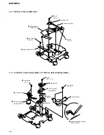
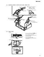
ADJUSTING PHASE OF MOTOR BLOCK ASSY, CAM (R) ASSY
4-5.
PHASE CHECK
4
two screws
(PTT2.6
×
6)
3
motor block assy
6
cam (R) assy
5
connector
(CN602)
black wiring
yellow wiring
1
Supply the power to the motor.
Voltage
: 9V
Yellow wiring : MOTOR –
Black wiring : MOTOR +
2
Motor stops at full open position.
full open position
–
+
7
two screws
(PTT2.6
×
6)
Note : Install the cam
in a
full open position
.
Note : Install the cam
in a
full open position
.
cam (R)
– Up view –
– Right side view –
1. Look into the position pointed by
!
in the
figure from the direction of the arrow.
2. Check that the hole (small) of the cam (R) is
within the range of
A
.
3. Check 2 with both L and R side.
If it is OK in both sides, the cam is in phase.
(If not, adjust it.)
#
#
A
cam (R)
hole (small)
bracket (R) assy
bracket (R) assy
chassis (MD) assy
look position
chassis (MD) assy
Summary of Contents for MDX-M690
Page 79: ...79 MDX M690 MEMO ...

