background image

28

MDX-CA680/CA680X

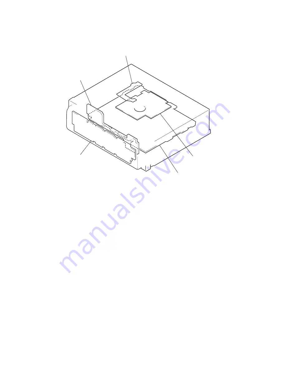
• Circuit Boards Location

SUB board

SENSOR board

SERVO board

MAIN board

KEY board

Summary of Contents for MDX-CA680

Page 1: ...rtion at 1 kHz 0 6 stereo 0 3 mono Separation 35 dB at 1 kHz Frequency response 30 15 000 Hz AM US model Tuning range 530 1 710 kHz Antenna terminal External antenna connector Intermediate frequency 10 7 MHz 450 kHz Sensitivity 30 µV Power amplifier section Outputs Speaker outputs sure seal connectors Speaker impedance 4 8 ohms Maximum power output 50 W 4 at 4 ohms General Outputs Audio outputs fr...

Page 2: ...aser diode in the optical pick up block may suffer electro static break down easily When handling it perform soldering bridge to the laser tap on the flexible board Also perform mea sures against electrostatic break down sufficiently before the op eration The flexible board is easily damaged and should be handled with care laser tap OPTICAL PICK UP FLEXIBLE BOARD 1 GENERAL Location of Controls 3 S...

Page 3: ...ton 22 m RESET button located on the front side of the unit behind the front panel 7 n Number buttons 3 REP 10 6 SHUF 10 13 14 16 17 o MODE button 9 11 13 14 16 p SOUND button 20 22 q AF button 1 15 17 r TA button 1 16 17 s OFF Stop Power off button 2 7 9 t ENTER button 11 14 18 8 10 11 12 13 17 18 21 2 W 1 AEP UK models only arning when installing in a car without an ACC accessory position on the...

Page 4: ...etting the clock The clock uses a 12 hour US model or 24 hour AEP UK models digital indication Example To set the clock to 10 08 1 Press MENU then press either side of DISC PRESET repeatedly until CLOCK appears 1Press ENTER The hour indication flashes 2Press either side of DISC PRESET to set the hour 3Press the side of SEEK The minute indication flashes 4Press either side of DISC PRESET to set the...

Page 5: ...you connect an optional power amplifier and do not use the built in amplifier the beep sound will be deactivated Tip 2 B For connecting two or more changers the source selector XA C30 optional is necessary Connection diagram 3 1 To a metal surface of the car First connect the black ground lead then connect the yellow and red power input leads 2 To the power antenna control lead or power supply lea...

Page 6: ... vitre arrière latérale voir Remarques sur les fils de commande et d alimentation 3 au niveau du AMP REMOTE IN de l amplificateur de puissance en option Ce raccordement s applique uniquement aux amplificateurs Le branchement de tout autre système risque d endommager l appareil 4 vers le cordon de liaison d un téléphone de voiture 5 à la borne 12 V qui est alimentée quand la clé de contact est sur ...

Page 7: ...e pieptoon uitgeschakeld Tip 2 B Om twee of meer CD MD wisselaars aan te sluiten hebt u de geluidsbronkiezer XA C30 optioneel nodig Aansluitschema 3 A Naar AMP REMOTE IN van een los verkrijgbare vermogensversterker Deze aansluiting is alleen bedoeld voor versterkers Door een ander systeem aan te sluiten kan het toestel worden beschadigd B Naar het interface snoer van een autotelefoon Opgelet Indie...

Page 8: ...façade sur la partie de l appareil comme indiqué sur l illustration puis appuyez sur le côté gauche jusqu au déclic Exemple de montage 5 Installation dans le tableau de bord Mounting the unit in a Japanese car 6 You may not be able to install this unit in some makes of Japanese cars In such a case consult your Sony dealer Note To prevent malfunction install only with the supplied screws 5 Warning ...

Page 9: ...are il diagramma del connettore di alimentazione ausiliaria della macchina per essere sicuri che le connessioni corrispondano correttamente Vi sono tre tipi di base illustrazione sotto Potrà essere necessario cambiare le posizioni dei conduttori rosso e giallo nel cavo di alimentazione dello stereo della macchina Dopo aver fatto corrispondere le connessioni e i cavi di alimentazione commutata coll...

Page 10: ...R ASSY Page 13 2 5 HEAT SINK Page 12 2 8 FLOAT BLOCK Page 13 SET Note 1 The process described in can be performed in any order Note 2 Without completing the process described in the next process can not be performed Note 3 Illustration of disassembly is omitted This set can be disassembled in the order shown below 2 1 DISASSEMBLY FLOW SECTION 2 DISASSEMBLY Note Follow the disassembly procedure in ...

Page 11: ...ANISM DECK MG 164MA 138 2 4 MAIN BOARD 1 screw PTT2 6 4 5 mechanism deck MG 164MA 138 3 two screws PTT2 6 4 4 bracket MD 2 connector CNP301 1 screw PTT2 6 4 1 three ground point screws PTT2 6 6 2 three screws PTT2 6 4 3 main board ...

Page 12: ...T SINK 2 6 SERVO BOARD 1 screw PTT2 6 10 1 two screws PTT2 6 10 2 two screws PTT2 6 16 3 heat sink 2 two screws BVTT2 4 1 optical pick up flexible board CN102 2 two screws BVTT2 4 1 flexible flat 11core cable CN103 3 servo board ...

Page 13: ...ote Take care not to scratch the optiocal pick up when pushing the cassette holder with a screwdriver etc shaft MD cover guide cassette holder A 1 four screws BVTT2 4 1 tension spring float B 6 float block 1 tension spring float B 2 two tension springs float F 3 Pushing an arrow A part raise the float block up ward at the front to release a lock A 4 float block lever lock R lever lock L 5 two damp...

Page 14: ...M903 2 10 LEVER LE23 ASSY 4 Remove the bracket LO in the direction of the arrow A bracket LO 1 Remove solders of motor M903 5 LO motor assy loading M903 2 tension spring rack 3 claw A bottom view 2 stopper washer 3 lever LE23 assy 4 roller gear E 1 ...

Page 15: ...p ring 1 5 3 lever lock L 2 type E stop ring 1 5 2 type E stop ring 1 5 4 Remove the holder assy in the direction of the arrow 1 spring chucking 1 spring chucking 3 lever lock R 2 12 CHUCKING ARM ASSY 1 Remove the chucking arm assy in the direction of the arrow holder assy ...

Page 16: ... screws K2 3 7 optical pick up KMS 241C 4 screw B2 3 2 14 SL MOTOR ASSY SLED M902 SP MOTOR ASSY SPINDLE M901 4 screw P1 7 1 8 5 bracket SL 9 two screws P1 7 1 8 0 bracket SP qa SP motor assy spindle M901 7 screw B2 3 2 two screws 2 8 3 sensor board 1 Remove solders of motors M901 M902 8 base SL 6 SL motor assy sled M902 ...

Page 17: ...FF button if the clock is not displayed 2 Push the preset 4 button 3 Push the preset 5 button 4 Press the preset 1 button for more than two seconds 5 Then the display indicates all lights the test mode is set Release the Test mode 1 Push the OFF button MD SECTION MD section adjustments are done automatically in this set TUNER SECTION Tuner section adjustments are done automatically in this set ...

Page 18: ...62 CLTV 61 FILO 60 FILI 59 PCO 57 RFI 58 AVSS 56 BIAS 55 AVDD 54 ASYI 53 ASYO 52 MVCI 51 D3 68 VC 67 AUX1 66 FE 65 ABCD 64 BOTM 63 PEAK 50 D2 49 D0 48 D1 47 XWE 46 XRAS 45 A09 44 XCAS 43 XOE 42 DVSS 41 A11 40 A08 39 A07 38 A06 37 A05 36 A04 35 A10 34 A00 33 A01 32 A02 31 A03 30 DVDD 28 XBCK 29 FS256 26 DADT 27 LRCK 24 XBCKI 25 ADDT 23 LRCKI 22 DATAI 21 DOUT 20 DIN1 19 DIN0 18 XTSL 17 OSCO 16 OSCI ...

Page 19: ...25 WBLADJ 24 VCC 23 3TADJ 22 EQADJ 21 VREF 20 F0CNT 19 XSTBY 18 XLAT 17 SCLK 16 SWDT 15 TEMPR 14 TEMPI 13 GND 12 APCREF 11 APC 10 PD 9 F 8 E 7 D 6 C 5 B 4 A 3 VC VI CONV BGR VREF SCRI PARA DECODE AUXSW COMMAND IVR GSW FF FBAL FF TG SEA 1 2 TG TEA WBL 3T EQ DET ADIP AGC WBL BPF22 BPFC ABCDA FEA WBL ATA CVB RFA1 1 2 1 2 GRVA OFST RFA2 GRV HLPT PTGR 2 1 1 2 BOTTOM PEAK RF AGC EQ EQ DET P P WBL 3T WBL...

Page 20: ...IVE AMP INTERFACE AMP AMP AMP VDD PSB AMP IC305 BA6287F 1 2 3 4 OUT1 VM VCC FIN 8 7 6 5 GND OUT2 VREF RIN CONTROL LOGIC TSD POWER SAVE DRIVER DRIVER IC307 MSM51V4400E 70TS K DATA BUS DQ3 DQ4 VSS 3 DQ2 2 A9 5 A0 9 A1 10 A2 11 A3 12 VCC 13 NC 6 NC 7 NC 8 DQ1 1 26 23 24 25 A8 NC NC NC 19 20 21 A6 A7 17 18 A4 A5 15 14 16 ROW DECODERS WORD DRIVERS MEMORY CELLS INTERNAL ADDRESS COUNTER TIMING GENERATOR ...

Page 21: ... CUT S H 25kHz LP DEMODULATOR STEREO ADJUST STEREO BLAND MULTIPATH DETECTOR D A CONVERTER PILOT CANCELATION PIL DET PLL AM FM NOISE BLANKER BEEP 80kHz LP 17 PULSE FORMER QUAL SUPPLY SECOND MAIN ACIN MONO FADER MONO FADER MONO FADER MONO FADER MONO FADER MONO FADER SUBWOOFER PHASE CONTROL MIXER OUTPUT SELECTOR FRONT REAR SW VDD SCL SDA GND SM QUAL MPOUT MPIN LEVEL MPX AMIF SEL SER FD1L FD1L FD1R FD...

Page 22: ... 57kHz 8th ORDER BAND PASS FILTER RDS RDBS DECODER RDS RDBS DEMODULATOR IIC BUS SLAVE TRANSCEIVER 17 18 CIN 19 LVIN 20 8 7 DATA CLOCK DATA CLOCK 4 4 5 9 10 3 4 5 IC505 BA8270F E2 1 2 3 4 5 6 7 8 9 10 14 13 12 11 BUS ON SWITCH RESET SWITCH BATTERY SWITCH BUS ON RST BATT CLK VREF DATA GND VCC RST BUS ON CLK IN BU IN DATA IN DATA OUT IC601 BA4908 V3 OVER VOLTAGE PROTECT REGULATOR 1 2 3 4 5 6 7 8 9 10...

Page 23: ...18 17 16 20 12 30 29 5 6 7 10 LD PD AMP I V AMP I V AMP FOCUS ERROR AMP TRACKING ERROR AMP RF AMP B P F PEAK BOTTOM 6 8 92 91 88 89 86 85 81 80 83 13 67 65 66 75 74 63 64 82 27 25 21 23 12 10 14 15 19 18 29 30 3 4 16 M M M AUTOMATIC POWER CONTROL DIGITAL SERVO SIGNAL PROCESS ANALOG MUX A D CONVERTER SERIAL PARALLEL CONVERTER DECODER AUTO SEQUENCER V I CONVERTER PEAK HOLD Q301 10 LEVEL SHIFT IC502 ...

Page 24: ...IIC BUS SLAVE TRANSCEIVER OSCILLATOR CLOCK X51 4 332MHz 4 8 5 OSCI OSCO SDA SCL DAVN 57 kHz BAND PASS FILTER CLOCKED COMPARATOR RDS RDBS DEMODULATOR DECODER SIGNAL QUALITY DECODER 16 18 19 MPX CIN 4 5 SC OUT MULTI PATH DETECTOR 20 2 LVIN MPTH 7 QUALITY 90 NS MASK BAND PASS FILTER IC20 Q22 NOISE DET DISCHARGE SWITCH DATA CLOCK DATA CLOCK MPX E AM F S METER H BU B EEP SIO SIGNAL PATH FM MW LW 18 SCL...

Page 25: ...479 D502 X501 18 432MHz X502 32 768kHz MD RST MD RST DEEMP I H INPUT MULTIPLEXER LOUDNESS MUTE MONO FADER MIXER OUTLF OUTLR R CH OUTPUT SELECTOR AM FM NOISE BLANKER R CH FL IN FL 1 CN601 1 2 POWER AMP IC611 FRONT L FR IN RL IN RR IN AUX IN 16 15 11 14 12 22 4 FL 9 FRONT L FR 4 FRONT R FR 12 FRONT R RL 2 REAR L RL 10 REAR L RR 3 REAR R RR 11 15 13 REAR R MUTE TEST TEL ATT STNBY BEEP AMPATT AMPON 5 ...

Page 26: ...N601 2 2 FU601 COM 8V AUDIO CIRCUIT B RST 3 BATT BATTERY SWITCH 10 B U C UNISI 50 UNISO UNICKIO MDMON 10 28 25 44 UNICKO 43 UNISI 42 UNISO 24 29 SIRCS 33 65 MD ON D301 TH600 D552 D701 LED810 LSW810 LED810 DISC SLOT ILLUMINATION VCC TUNER 5 6V TUNER 8 7V VCC 7 7 ACC B SWITCH Q665 6V REGULATOR Q331 3 3V REGULATOR IC401 Q401 5V REGULATOR Q336 B SWITCH Q402 403 3 3V D612 D613 BU B 2 3 4 9 BU B 5 10 11...

Page 27: ... are in µF unless otherwise noted pF µµF 50 WV or less are not indicated except for electrolytics and tantalums All resistors are in Ω and 1 4 W or less unless otherwise specified f internal component C panel designation A B Line Power voltage is dc 14 4V and fed with regulated dc power supply from ACC and BATT cords Voltages are taken with aVOM Input impedance 10 MΩ Voltage variations may be note...

Page 28: ...28 MDX CA680 CA680X Circuit Boards Location SUB board SENSOR board SERVO board MAIN board KEY board ...

Page 29: ...501 R540 R542 R519 C513 R520 R521 C352 R401 R402 R403 L301 C344 R101 C101 R201 C201 C514 C515 R533 C504 C505 R534 R510 R512 C503 C506 L501 1 4 8 5 IC305 Q402 B C E C359 R332 R335 C317 C309 C307 C316 C350 C358 C301 C356 C357 C362 IC307 R333 R334 C351 C333 SERVO BOARD CONDUCTOR SIDE 1 680 396 12 12 1 11 SENSOR BOARD COMPONENT SIDE 1 680 397 12 12 M903 LOADING M M BLK RED BLK RED M902 SLED M M M901 S...

Page 30: ...s See page 18 for IC Block Diagrams Voltages and waveforms are dc with respect to ground under no signal conditions no mark MD PLAY Impossible to measure The components identified by mark 0 or dotted line with mark 0 are critical for safety Replace only with part number specified Page 31 ...

Page 31: ...SCHEMATIC DIAGRAM SERVO Section 2 2 See page 40 for Waveforms See page 18 for IC Block Diagram Voltages and waveforms are dc with respect to ground under no signal conditions no mark MD PLAY Impossible to measure Page 30 Page 34 ...

Page 32: ...01 G 13 IC602 J 11 IC611 B 8 Q21 I 1 Q22 J 3 Q331 H 13 Q333 I 12 Q335 H 13 Q336 H 13 Q431 C 5 Q441 C 5 Q451 C 4 Q461 C 4 Q478 E 8 Q479 E 8 Q560 E 13 Q631 E 11 Q651 E 11 Q662 J 14 Q663 I 14 Q664 L 10 Q665 K 13 Q701 E 13 1 9 WHT BLK WHT GRN BLK GRN VIO BLK VIO GRY BLK GRY BLU WHT BLU RED YEL BLK FRONT LCH FRONT LCH REAR LCH REAR LCH REAR RCH REAR RCH FRONT RCH FRONT RCH AMP REM ANT REM ACC BATT GND ...

Page 33: ...3 4 10 SCHEMATIC DIAGRAM MAIN Board 1 3 See page 40 for Waveform See page 18 for IC Block Diagrams Voltages and waveforms are dc with respect to ground under no signal detuned conditions no mark FM AM MW LW Page 34 Page 35 ...

Page 34: ...0 CA680X 34 34 4 11 SCHEMATIC DIAGRAM MAIN Board 2 3 See page 40 for Waveforms Voltages and waveforms are dc with respect to ground under no signal detuned conditions no mark FM AM MW LW Page 31 Page 33 Page 35 ...

Page 35: ...A680 CA680X 35 35 4 12 SCHEMATIC DIAGRAM MAIN Board 3 3 See page 18 for IC Block Diagrams Voltages are dc with respect to ground under no signal detuned conditions no mark FM MD PLAY Page 33 Page 34 Page 37 ...

Page 36: ...MDX CA680 CA680X 36 36 4 13 PRINTED WIRING BOARD SUB Board See page 28 for Circuit Boards Location LED810 LSW810 A1 S1 A2 K1 S2 K2 K1 S2 K2 A1 S1 A2 K A K A Page 32 Page 38 ...

Page 37: ...MDX CA680 CA680X 37 37 4 14 SCHEMATIC DIAGRAM SUB Board Page 35 Page 39 ...

Page 38: ...A A 6 1 5 2 4 3 6 1 5 2 4 3 6 1 5 2 4 3 3 4 2 5 1 6 3 4 2 5 1 6 3 4 2 5 1 6 3 4 2 5 1 6 6 1 5 2 4 3 6 1 5 2 4 3 A K A K K A K A 1 2 4 3 4 3 5 2 6 1 4 3 5 2 6 1 K K A K A K A A B C D E F G 1 2 3 4 5 6 7 8 9 10 11 12 13 A Ref No Location Ref No Location Semiconductor Location D902 G 12 D903 G 12 D904 G 11 D906 G 11 D908 G 11 D971 B 11 IC900 F 8 IC971 A 11 LED900 B 2 LED901 C 2 LED902 B 1 LED903 C 1 ...

Page 39: ...MDX CA680 CA680X 39 39 4 16 SCHEMATIC DIAGRAM KEY Board See page 40 for Waveform Voltages and waveforms are dc with respect to ground under no signal detuned conditions no mark FM Page 37 ...

Page 40: ... qs IC101 6 BCK MD Play Mode qd IC501 es XTAL 6 IC301 wj LRCK MD Play Mode 4 IC302 ef FE MD Play Mode 5 IC302 wh TE MD Play Mode 510 mVp p 480 mVp p 1 3 Vp p Approx 150 mVp p Approx 1 Vp p 3 4 Vp p 22 8 µs 4 7 Vp p 354 ns 4 6 Vp p 88 ns 3 3 Vp p 22 8 µs 3 2 Vp p 354 ns 4 4 Vp p 100 ns MAIN Board wa IC51 4 OSCO ws IC501 qs OSCOUT wd IC501 qh XOUT KEY Board wf IC900 uf OSC 5 3 Vp p 231 ns 2 5 Vp p 2...

Page 41: ... on off output Not used fixed at L 16 OSCI I System clock signal 1024Fs 45 MHz input from the oscillator circuit 17 OSCO O System clock signal 1024Fs 45 MHz output terminal Not used open 18 XTSL I Input terminal for the system clock frequency setting L 45 1584 MHz H 22 5792 MHz fixed at L in this set 19 DIN0 I Digital audio signal input terminal when recording mode Not used fixed at L 20 DIN1 I Di...

Page 42: ... input from the CXA2523AR IC302 69 ADIO O A Monitor output of the A D converter input signal Not used open 70 AVDD Power supply terminal 3 3V analog system 71 ADRT I A A D converter operational range upper limit voltage input terminal fixed at H in this set 72 ADRB I A A D converter operational range lower limit voltage input terminal fixed at L in this set 73 AVSS Ground terminal analog system 74...

Page 43: ...e servo drive PWM signal output to the BH6518FS IC303 94 SPFD O Spindle servo drive PWM signal output to the BH6518FS IC303 95 FGIN I 96 TEST1 I 97 TEST2 I 98 TEST3 I 99 DVSS Ground terminal digital system 100 EFMO O EFM signal output terminal when recording mode Not used open I A for analog input O 3 for 3 state output and O A for analog output in the column I O Input terminal for the test fixed ...

Page 44: ...rminal for the internal circuit BPF3T 24 VCC Power supply terminal 3 3V 25 WBLADJ I Center frequency setting terminal for the internal circuit BPF22 26 TE O Tracking error signal output to the CXD2662R IC301 27 CSLED I Connected to the external capacitor for low pass filter of the sled error signal 28 SE O Sled error signal output to the CXD2662R IC301 29 ADFM O FM signal output of the ADIP 30 ADI...

Page 45: ...r D RAM capacitance 2M bit or 4M bit L 4M bit external D RAM H 2M bit internal D RAM of CXD2652AR fixed at L in this set 24 25 O Not used open 26 MNT0 I Focus OK signal input from the CXD2662R IC301 H is input when focus is on L NG 27 MNT1 I Track jump detection signal input from the CXD2662R IC301 28 MNT2 I Busy monitor signal input from the CXD2662R IC301 29 MNT3 I Spindle servo lock status moni...

Page 46: ...CM1718E IC101 CXD2662R IC301 and BH6518FS IC303 L reset 60 BU IN I Battery detect signal input from the SONY bus interface IC505 and battery check circuit H battery on 61 BUS ON I SONY bus on off control signal input from the system controller IC501 L bus on 62 SQSY I Subcode Q sync SCOR input from the CXD2662R IC301 L is input every 13 3 msec Almost all H is input 63 C SW I Inputs a disc loading ...

Page 47: ...play driver IC900 19 LCDCE O Chip enable signal output to the liquid crystal display driver IC900 H active 20 LCDCKO O Serial data transfer clock signal output to the liquid crystal display driver IC900 21 to 23 NC O Not used open 24 SYSRST O Reset signal output to the SONY bus interface IC505 L reset 25 BUSON O Bus on off control signal output to the SONY bus interface IC505 L bus on 26 KEYACK I ...

Page 48: ...DX CA680 fixed at L MDX CA680X fixed at H 77 COLSEL I Setting terminal for the illumination color L amber H green MDX CA680 not used fixed at L MDX CA680X fixed at H 78 DIMSEL I Setting terminal for the dimmer L no dimmer H dimmer in fixed at L in this set 79 to 85 NCO O Not used open 86 EEP SIO I O Two way data EEPROM bus with the FM AM tuner unit TU10 87 EEP CKO O EEPROM bus clock signal output ...

Page 49: ...4 15 16 9 11 10 12 Ref No Part No Description Remark Ref No Part No Description Remark 1 X 3378 458 1 PANEL ASSY SUB 2 X 3376 699 1 GEAR ASSY 3 3 030 909 01 DAMPER OIL 4 3 713 786 51 SCREW P 2X3 5 3 040 990 01 BUTTON EJECT Z 6 3 034 086 01 SPRING DOOR 7 3 033 750 01 DOOR MD 8 1 680 042 11 SUB BOARD 9 3 376 464 11 SCREW PTT 2 6X6 GROUND POINT 10 3 041 017 01 BRACKET MD 11 3 223 782 01 COVER 12 A 32...

Page 50: ...BUTTON 4 6 4 5 6 57 3 223 791 01 BUTTON MENU SOUND 58 3 223 789 01 BUTTON DSPL SCRL D S 59 3 223 790 01 BUTTON LIST ENTER 60 3 223 792 01 BUTTON AF TA OFF AEP UK 60 3 223 792 11 BUTTON AF TA OFF OFF US 61 3 223 799 01 PLATE LCD GROUND 62 3 223 800 01 ILLUMINATOR LCD 63 3 223 797 01 PLATE LCD LIGHT GUIDE 64 1 694 780 11 CONDUCTIVE BOARD CONNECTION 65 3 223 798 01 HOLDER LCD 66 X 3380 079 1 PANEL AS...

Page 51: ...SSY 107 3 032 682 01 SPRING HOLDER 108 3 034 301 01 CUSHION EJ2 109 3 034 302 01 CUSHION EJ3 110 3 032 712 01 LEVER LOCK R 111 3 919 281 01 SPRING CHUCKING 112 X 3379 368 1 COVER ASSY MD 113 3 035 932 01 WASHER STOPPER 114 X 3379 362 1 LEVER LE23 ASSY 115 3 032 707 01 SPRING LEVER LE 116 3 925 034 01 ROLLER GEAR E 117 X 3376 798 1 ARM ASSY CHUCKING 118 3 032 711 01 LEVER LOCK L 119 3 220 096 01 BR...

Page 52: ... 297 01 BRACKET SP 157 A 3315 218 A CHASSIS OP ASSY 158 3 032 660 01 BRACKET LO 159 3 032 669 01 SPRING RACK TENSION 160 3 032 705 01 BEARING SL 161 X 3373 213 1 SCREW ASSY FEED 162 3 939 590 07 SCREW IB LOCK 163 3 010 091 01 SPRING SL FEED 164 3 919 293 01 SHAFT OPT S GUIDE 0165 8 583 065 03 OPTICAL PICK UP KMS 241C J1RP 166 3 920 537 01 SHAFT OPT L GUIDE M901 A 3301 407 A MOTOR ASSY SP SPINDLE M...

Page 53: ...ne service Some delay should be anticipated when order ing these items SEMICONDUCTORS In each case u µ for example uA µA uPA µPA uPB µPB uPC µPC uPD µPD CAPACITORS uF µF COILS uH µH The components identified by mark 0 or dotted line with mark 0 are critical for safety Replace only with part number specified When indicating parts by reference number please include the board LED901 8 719 061 16 LED ...

Page 54: ... 2 2K 5 1 16W R909 1 216 827 11 METAL CHIP 3 3K 5 1 16W R910 1 216 829 11 METAL CHIP 4 7K 5 1 16W R911 1 216 864 11 SHORT 0 AEP UK R912 1 216 831 11 METAL CHIP 6 8K 5 1 16W AEP UK R913 1 216 833 11 METAL CHIP 10K 5 1 16W AEP UK R914 1 216 819 11 METAL CHIP 680 5 1 16W R915 1 216 819 11 METAL CHIP 680 5 1 16W R916 1 216 821 11 METAL CHIP 1K 5 1 16W R917 1 216 823 11 METAL CHIP 1 5K 5 1 16W R918 1 2...

Page 55: ...A 3283 065 A MAIN BOARD COMPLETE CA680X AEP UK 3 040 998 01 BRACKET IC 3 041 011 01 HEAT SINK REG 3 223 780 11 HEAT SINK 3 223 783 01 CHASSIS BACK 7 685 647 79 SCREW BVTP 3X10 TYPE2 N S 7 685 793 09 SCREW PTT 2 6X8 S 7 685 794 09 SCREW PTT 2 6X10 S 7 685 797 09 SCREW PTT 2 6X16 S CAPACITOR C11 1 162 918 11 CERAMIC CHIP 18PF 5 50V C13 1 162 964 11 CERAMIC CHIP 0 001uF 10 50V US C14 1 104 665 11 ELE...

Page 56: ...10PF 0 5PF 50V AEP UK C506 1 162 915 11 CERAMIC CHIP 12PF 5 50V US C507 1 162 915 11 CERAMIC CHIP 10PF 0 5PF 50V C508 1 107 826 11 CERAMIC CHIP 0 1uF 10 16V C511 1 162 970 11 CERAMIC CHIP 0 01uF 10 25V MAIN C512 1 162 927 11 CERAMIC CHIP 100PF 5 50V C541 1 162 970 11 CERAMIC CHIP 0 01uF 10 25V C551 1 162 970 11 CERAMIC CHIP 0 01uF 10 25V C553 1 162 927 11 CERAMIC CHIP 100PF 5 50V C561 1 162 927 11...

Page 57: ...ORT 0 JC27 1 216 296 11 SHORT 0 JC28 1 216 296 11 SHORT 0 JC29 1 216 296 11 SHORT 0 JC30 1 216 864 11 SHORT 0 JC33 1 216 296 11 SHORT 0 JC34 1 216 296 11 SHORT 0 JC35 1 216 296 11 SHORT 0 JC37 1 216 296 11 SHORT 0 JC41 1 216 296 11 SHORT 0 AEP UK JC42 1 216 296 11 SHORT 0 AEP UK JC43 1 216 296 11 SHORT 0 AEP UK JC44 1 216 296 11 SHORT 0 JC45 1 216 296 11 SHORT 0 JC47 1 216 296 11 SHORT 0 JC48 1 21...

Page 58: ... 2K 5 1 16W R473 1 216 821 11 METAL CHIP 1K 5 1 16W R474 1 216 833 11 METAL CHIP 10K 5 1 16W R479 1 249 401 11 CARBON 47 5 1 4W R480 1 216 295 11 SHORT 0 R482 1 216 295 11 SHORT 0 R501 1 216 837 11 METAL CHIP 22K 5 1 16W R502 1 216 813 11 METAL CHIP 220 5 1 16W R504 1 216 821 11 METAL CHIP 1K 5 1 16W R505 1 216 821 11 METAL CHIP 1K 5 1 16W R506 1 216 821 11 METAL CHIP 1K 5 1 16W R507 1 216 841 11 ...

Page 59: ... CERAMIC CHIP 100PF 5 50V C309 1 162 968 11 CERAMIC CHIP 0 0047uF 10 50V C310 1 117 863 11 CERAMIC CHIP 0 47uF 10 6 3V C311 1 164 245 11 CERAMIC CHIP 0 015uF 10 25V C314 1 107 826 11 CERAMIC CHIP 0 1uF 10 16V C315 1 125 837 11 CERAMIC CHIP 1uF 10 6 3V C316 1 107 826 11 CERAMIC CHIP 0 1uF 10 16V C317 1 107 826 11 CERAMIC CHIP 0 1uF 10 16V C318 1 104 852 11 TANTALUM CHIP 22uF 20 6 3V C319 1 104 852 ...

Page 60: ...5 1 16W R320 1 216 855 11 METAL CHIP 680K 5 1 16W R324 1 216 827 11 METAL CHIP 3 3K 5 1 16W R325 1 216 821 11 METAL CHIP 1K 5 1 16W R327 1 216 821 11 METAL CHIP 1K 5 1 16W R328 1 216 811 11 METAL CHIP 150 5 1 16W R329 1 216 819 11 METAL CHIP 680 5 1 16W R330 1 216 853 11 METAL CHIP 470K 5 1 16W R331 1 216 809 11 METAL CHIP 100 5 1 16W R332 1 216 809 11 METAL CHIP 100 5 1 16W R333 1 216 819 11 META...

Page 61: ... LED LED810 8 719 082 38 LED CL 270SR C TS DISC SLOT ILLUMINATION CA680X LED810 8 719 082 40 LED CL 270FG C TS DISC SLOT ILLUMINATION CA680 SWITCH LSW810 1 771 883 11 SWITCH TACTILE WITH LED Z CA680X LSW810 1 786 113 11 SWITCH TACT WITH LED Z CA680 MISCELLANEOUS 22 1 792 195 11 CABLE FLEXIBLE FLAT 14 CORE 24 1 776 207 82 CORD WITH CONNECTOR POWER US 24 1 776 527 61 CORD WITH CONNECTOR ISO POWER AE...

Page 62: ...924 961 01 SUPPORT ND FITTING US 507 1 776 207 82 CORD WITH CONNECTOR POWER US 508 X 3366 405 1 SCREW ASSY EXP FITTING AEP UK 509 1 465 459 21 ADAPTER ANTENNA AEP UK 510 1 776 527 61 CORD WITH CONNECTOR ISO POWER AEP UK 501 502 503 FRAME ASSY 1 COLLAR 1 FITTING SPRING 2 504 T4 12 1 P4 6 1 FITTING SCREW ASSY K5 8 4 506 507 FITTING SUPPORT ND 1 POWER CORD 1 508 FITTING SCREW 1 BUSHING 1 FITTING SCRE...

Page 63: ...63 MDX CA680 CA680X MEMO ...

Page 64: ...llows you to jump to the revised page Also clicking the version at the upper right on the revised page allows you to jump to the next revised page Ver Date Description of Revision 1 1 2001 05 Change of Part No for SPRING FITTING ECN CSA04727 1 0 2001 02 New ...

Reviews: