


Connecting Video Monitors
19
P
repa
ra
ti
ons
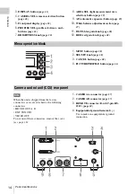
The camera output picture is output from all of
the video output connectors (VIDEO OUT, and
HD SDI OUT A, B connectors) on the CCU rear
panel.
Signals picked up by camera A are output from
the HD SDI OUT A connector, and signals picked
up by camera B are output from the HD SDI OUT
B connector.
The VIDEO OUT connector outputs signals from
camera A when CAMERA SEL is set to A or
BOTH, and signals from camera B when
CAMERA SEL is set to B.
You can check the camera output picture by
connecting a monitor that supports the respective
output signal to any of the connectors.
Notes
• Before connecting the cables, press the On/
Standby (
1
) button to set the unit to the standby
state.
• Connect a video monitor to each connector only
via a cable. If you use a conversion adaptor, the
camera output picture is not output correctly.
To select the output mode (aspect ratio) for SD
signal
When using an SD signal down-converted for
output from the VIDEO OUT connector, you can
select the output mode in “Down Converter”
of the VIDEO SET menu.
Squeeze:
To horizontally reduce a 16:9 picture to
output a 4:3 picture
Letterbox:
To mask the upper and lower areas of
a 4:3 picture to display a shrunken 16:9
picture in the center of the screen
Edge Crop:
To cut the both sides of a 16:9
picture to output a 4:3 picture
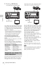
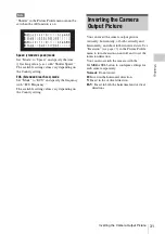
Connecting Video Monitors
a) 75
Ω
coaxial cable
b) Component video cable with BNC connectors
Video monitor
SDI input connector
a)
b)
CCU
b)
Summary of Contents for MCC3000MT
Page 56: ...Sony Corporation ...


