background image


20

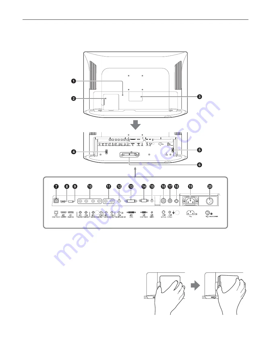
Rear Panel

To use the connectors on the rear panel, remove the cable cover. For details on the cable cover, see 
page 23.

Cable cover (L)

When connecting or disconnecting the cable of 
the connector on the rear panel, remove this 
cover.
Make sure to disconnect the power cord before 
connecting or disconnecting connectors.
While the unit is operated, the temperature of 
the connectors may become high. Touching the 
connectors may burn your hand.
Before connecting or disconnecting connectors, 
disconnect the power cord, then wait until the 
unit cools down sufficiently.

Cable cover (M)

This cover is specifically for the 12G-SDI 1 input/
output connector. Pull the cover open with your 
finger hooked in the concave area near 

 on the 

cover while pressing the tab at the edge of the 
cover to the right. The cable of the 12G-SDI 1 
input/output connector can be connected or 
disconnected without removing the cable cover 
(L).

Summary of Contents for LMD-XH320MT

Page 1: ...5 017 230 12 1 LCD Monitor Instructions for Use Before operating the unit please read this manual thoroughly and retain it for future reference LMD XH320MT 2021 Sony Corporation 2022 02 ...

Page 2: ...the product Safety sign Follow the warnings in the instructions for use for parts of the unit on which this symbol appears NOTE Background color Blue Symbol White Consult the instructions for use Follow the directions in the instructions for use for parts of the unit on which this symbol appears This symbol indicates the manufacturer and appears next to the manufacturer s name and address This sym...

Page 3: ...nvironments 1 All devices connected to the unit must be certified or compliant according to IEC 60601 1 IEC 60950 1 and IEC 60065 standards and other IEC ISO standards applicable to the devices 2 Furthermore the system as a whole must comply with IEC 60601 1 standards All peripheral devices connected to the signal input output sections of the unit constitute the medical use system and therefore th...

Page 4: ... replacement parts sold by Sony Corporation may result in increased emissions or decreased immunity of the LMD XH320MT Guidance and manufacturer s declaration electromagnetic emissions The LMD XH320MT is intended for use in the electromagnetic environment specified below The customer or the user of the LMD XH320MT should assure that it is used in such an environment Emission test Compliance Electr...

Page 5: ... 2 kV common mode Mains power quality should be that of a typical commercial or hospital environment Voltage dips short interruptions and voltage variations on power supply input lines IEC 61000 4 11 0 UT 100 dip in UT for 0 5 1 cycles a 40 UT 60 dip in UT for 5 cycles 70 UT 30 dip in UT for 25 30 cycles a for 0 5 sec 0 UT 100 dip in UT for 250 300 cycles a for 5 sec Not applicable 0 UT 100 dip in...

Page 6: ...s c 3 Vrms d 1 2 ƊP 6 Vrms 150 kHz to 80 MHz in ISM bands c 6 Vrms Radiated RF IEC 61000 4 3 3 V m 80 MHz to 2 7 GHz 3 V m IEC 60601 1 2 2007 d 1 2 ƊP 80 MHz to 800 MHz d 2 3 ƊP 800 MHz to 2 5 GHz IEC 60601 1 2 2014 d 2 0 ƊP 80 MHz to 2 7 GHz Where P is the maximum output power rating of the transmitter in watts W according to the transmitter manufacturer and d is the recommended separation distan...

Page 7: ... in which radiated RF disturbances are controlled The customer or the user of the LMD XH320MT can help prevent electromagnetic interference by maintaining a minimum distance between portable and mobile RF communications equipment transmitters and the LMD XH320MT as recommended below according to the maximum output power of the communications equipment Rated maximum output power of transmitter W Se...

Page 8: ...tion 18 Hz 27 V m 27 V m 430 470 MHz GMRS 460 FRS 460 FM 5 kHz deviation 1 kHz sine 28 V m 28 V m 704 787 MHz LTE Band 13 17 Pulse modulation 217 Hz 9 V m 9 V m 800 960 MHz GSM 800 900 TETRA 800 iDEN 820 CDMA 850 LTE Band 5 Pulse modulation 18 Hz 28 V m 28 V m 1 700 1 990 MHz GSM 1800 CDMA 1900 GSM 1900 DECT LTE Band 1 3 4 25 UMTS Pulse modulation 217 Hz 28 V m 28 V m 2 400 2 570 MHz Bluetooth WLA...

Page 9: ...n t exceed the surface s edges If not this apparatus may lean or fall over and cause an injury Warning To prevent injury if mounting the unit using a mounting arm wall fixture or other mounting device prepared by the customer mount the unit securely as described in the instruction manual provided with the mounting device Check beforehand that the mounting device used has sufficient strength to sup...

Page 10: ...the hazardous substances restriction of India s E Waste Management Rules The maximum allowable concentrations of the restricted substances are 0 1 by weight in homogenous materials for Lead Mercury Hexavalent Chromium Polybrominated Biphenyls PBB and Polybrominated Diphenyl Ethers PBDE and 0 01 by weight in homogenous materials for Cadmium except for the exemptions specified in Schedule II of the ...

Page 11: ...Repacking 15 Features 15 Location and Function of Parts and Controls 17 Front Panel 17 Input Signals and Adjustable Setting Items 19 Rear Panel 20 Preparation 23 Connecting 23 Turning on the Monitor Switching Input Settings 25 Initial Setting 25 Using the Menu 26 Adjustment Using the Menus 28 Items 28 Adjusting and Changing the Settings 28 Color Tone Adjustment menu 28 Screen Control menu 29 3D Se...

Page 12: ... if necessary Avoid using this unit while walking or exercising or in areas that shake violently as doing so can increase the chances of feelings of discomfort When connecting the unit to medical equipment refer to Precautions when connecting this unit to medical equipment Precautions when connecting this unit to medical equipment Before using this unit for medical purposes be sure to confirm that...

Page 13: ...uck either always off black always on red green or blue or flashing In addition over a long period of use because of the physical characteristics of the liquid crystal display such stuck pixels may appear spontaneously These problems are not a malfunction Do not leave the LCD screen facing the sun as it can damage the LCD screen Take care when you place the unit by a window Do not push or scratch ...

Page 14: ...r cooling the unit is built in When the fan error indication appears on the screen turn off the power and contact an authorized Sony dealer On Temperature Error When this unit is used in a high temperature environment and the internal temperature rises a temperature error is displayed on the screen When the temperature error is displayed contact an authorized Sony dealer On condensation If the uni...

Page 15: ...f On Repacking Do not throw away the carton and packing materials They make an ideal container which to transport the unit If you have any questions about this unit contact your authorized Sony dealer Features This monitor displays color video images that are output from medical imaging systems on the LCD panel LCD panel consists of liquid crystal color filters and LED backlights The panel display...

Page 16: ... 3D glasses optimized for this unit are supplied considering long time work You can use it for both 2D and 3D with the 2D 3D selection function Flat surface for better maintenance The design allows the user to easily wipe liquids and gel off the LCD panel and control buttons ensuring a high standard of disinfection and cleanliness ...

Page 17: ...nnector assigned to the PORT A B is displayed 2 or 3 screen display setting buttons PIP POP For displaying the 2 or 3 screen display or switching the 2 or 3 screen display mode SWAP For swapping between the main display and the sub display If the combination of input signals assigned to each port is set to 12G SDI 1 and 12G SDI 2 or HDMI and Display Port the 2 or 3 screen display is not available ...

Page 18: ...The following functions are assigned in the default setting CUSTOM 1 Brightness CUSTOM 2 Contrast 2D 3D select button Switches between 2D and 3D displays OSD menu operation buttons MENU button Press to display the on screen menu Press again to hide the menu buttons Press to select the items and setting values CONTROL button Displays or hides the operation buttons on the front panel Selects the ite...

Page 19: ... applied to the screen Item Input signal HDMI Display Port SDI DVI D Video PC Video PC 12G SDI 1 2 3G SDI Video PC Gamma Phase Chroma Brightness Contrast A I M E A I M E Structure A I M E Color A I M E Shadow Color Temperature Gain R G B Offset Bias R G B Offset Mono Sharpness H Sharpness V RGB Range Color Space 4K Scan Size 3 3 HD Scan Size 2 2 2 SD Scan Size 2 2 2 4K Zoom Flip Pattern SD Aspect ...

Page 20: ...mperature of the connectors may become high Touching the connectors may burn your hand Before connecting or disconnecting connectors disconnect the power cord then wait until the unit cools down sufficiently Cable cover M This cover is specifically for the 12G SDI 1 input output connector Pull the cover open with your finger hooked in the concave area near on the cover while pressing the tab at th...

Page 21: ...tor Inputs the HDMI signals Use the Premium High Speed cable that is shorter than 3 m meters with the cable type logo Cables manufactured by Sony are recommended Display Port input connector Inputs the Display Port signal Display Port is an interface developed by VESA that supports transfer of both video and audio digital signals on a single cable Use the DisplayPort standard version 1 2 certified...

Page 22: ...nput connector support HDCP a copy protection technology that incorporates coding technology for digital video signals SERIAL REMOTE RS 232C connector D sub 9 pin female Connect to the RS 232C control connector on the external equipment connected to the monitor The monitor can be operated according to control commands sent from connected external equipment REMOTE connector Stereo mini jack The mon...

Page 23: ...e damaged or the monitor may fall over 3 Connect the connection cable The connection cable should be wired with the cable holder 4 Connect the AC power cord When using the supplied AC power cord Slide the shutter of the AC power connector to show the AC input connector and plug the AC power cord into the AC input connector When using the optional AC adaptor Slide the shutter to show the DC input c...

Page 24: ...able cover and it cannot be fit in do not secure it in the cable holder and use the cable with the cable cover removed Caution This unit with the cable covers attached conforms to the waterproofed standard See page 37 Be sure not to use the unit with the cable covers removed since waterproofed performance is not guaranteed Cautions for splash proof performance Splash proof test has been conducted ...

Page 25: ...he first time after purchasing it select the area and language where you intend to use this unit To set the using area 1 Turn on the unit The Area Setting screen appears 2 Press the CONTROL button 3 Press the or button to select the area where you intend to use the unit and press the button 4 When the confirmation screen is displayed press the or button to select Yes and press the CONTROL button T...

Page 26: ...nd press the CONTROL button The menu changes to the selected language To change the menu language Change the menu language on the menu screen For details refer to Language page 33 in the System Configuration menu Using the Menu The unit is equipped with an on screen menu for making various adjustments and settings such as picture control input setting setting change etc 1 Press the CONTROL button ...

Page 27: ...ock is set to On the setting cannot be changed For details about Control Lock see page 32 To hide the menu Press the MENU button The menu disappears automatically if a button is not pressed for one minute To hide the operation buttons Press the CONTROL button About the storage of the settings The adjusted settings are automatically stored in the monitor memory For details on settings for the next ...

Page 28: ...lipping Size Sub Screen Position Pattern Skip Input Output Configuration page 31 Clone Out Port A Input Select Port B Input Select Input Name AUX IN Setting Power Supply System Configuration page 32 Control Lock OSD Setting Power On Setting Power Save Serial Remote Remote Ethernet Setting Custom Button Panel Display A I M E Setting Monitor Information Initial Setup page 34 Language Port A Input Se...

Page 29: ...ffset Gain B Offset Adjust color temperature in detail and color balance Gain Bias R Offset Bias G Offset Bias B Offset Adjust color temperature in detail and color balance Bias Mono Sets the display to a monochrome picture Set to On for a monochrome picture set to Off for a normal chromatic picture Sharpness H Adjusts the horizontal sharpness The higher the setting the sharper the picture The low...

Page 30: ...creen display the sub screen displays in 2D Menu Setting 3D Signal Format Select the 3D signal format Single Cable DS Select to display signals of the 3G Level B Dual Stream system in 3D Use a single SDI cable Dual Cable DS Select to display signals of the Dual Stream system in 3D Input signals to the 12G SDI 1 2 connectors by using two SDI cables Side by Side Select to display signals of the Side...

Page 31: ...lor gamut from Auto BT 709 or BT 2020 When Auto is selected the color gamut changes according to the resolution set in Format When 3840 2160 is selected clone out SDI signal is output with the BT 2020 setting When 1920 1080 is selected it is output with the BT 709 setting 2D 3D Output Select 2D or 3D output mode 2D Outputs a 2D image 3D Outputs a 3D Line by Line image Auto Automatically switches t...

Page 32: ... the control lock setting OSD Setting Menu Position Sets the screen position for the OSD menu Status Display Select Port Input Connector Name Control Lock Signal Format Scan Size 4K Zoom Flip Pattern PIP POP Mode A I M E Energy Saving Mode and 2D 3D Display are displayed Menu Setting Auto The format and scan mode are displayed temporarily when the content of Status Display is changed On The format...

Page 33: ... the using mode Off Inactivates the serial remote function RS 232C Controls this unit via RS 232C command Ethernet Controls this unit via Ethernet command Menu Setting Remote Remote Mode Sets the remote function when the REMOTE connector is connected to the optional Foot Switch FS 24 Off Inactivates the remote function Port A B Switches between PORT A and PORT B PIP POP Switches between the single...

Page 34: ...connector that is skipped when changing the input signal by pressing the PORT A button Set to Not Skip or Skip for the 12G SDI 1 12G SDI 2 3G SDI Display Port HDMI DVI D connector Menu Setting Port B Input Select Sets the input connector that is skipped when changing the input signal by pressing the PORT B button Set to Not Skip or Skip for the 12G SDI 1 12G SDI 2 3G SDI Display Port HDMI DVI D co...

Page 35: ...al aspect ratio is different from that of the panel the black bars appear This is not a failure of the unit While the logo is displayed the operation buttons do not operate when pushed While the logo is displayed the operation buttons do not operate After the logo disappears the operation buttons can be operated The logo display time can be set in the menu page 33 The display is dark When the unit...

Page 36: ...jack 1 AC input connector 100 V to 240 V 50 60 Hz DC input connector DC 26 V Output 3G SDI output connector BNC type 1 Active through 12G SDI 1 2 output connector BNC type 2 Active through CLONE OUT connector BNC type 1 DC 5V OUT Round type pin female 1 DC 12V OUT Round type pin female 1 General Power AC IN 100 V 240 V 50 60 Hz 2 4 A 1 1 A DC IN 26 V 8 8 A Supplied from AC adaptor Power consumptio...

Page 37: ...rs are attached Degree of safety in the presence of a flammable anesthetic mixture with air or with oxygen or nitrous oxide Not suitable for use in the presence of a flammable anesthetic mixture with air or with oxygen or nitrous oxide Mode of operation Continuous Design and specifications are subject to change without notice Notes Always verify that the unit is operating properly before use SONY ...

Page 38: ...ereo mini jack connector 5V 2 0A DC output connector 12V 2 5A DC output connector Pin number Signal 1 NC 2 RX 3 TX 4 NC 5 GND 6 NC 7 NC 8 NC 9 NC Pin number Signal 1 GND 2 On short to sleeve Off open 3 NC Pin number Signal 1 5 V 2 NC 3 GND Pin number Signal 1 GND 2 NC 3 12 V 4 NC ...

Page 39: ...YCbCr 10bit 1280 720 50p 4 2 2 YCbCr 10bit 3G SDI 1920 1080 60p 1 4 2 2 YCbCr 10bit Level A Level B DL 1920 1080 50p 4 2 2 YCbCr 10bit Level A Level B DL 1920 1080 60i 1 4 2 2 YCbCr 10bit Level B DS 3D Dual Stream 1920 1080 50i 4 2 2 YCbCr 10bit Level B DS 3D Dual Stream 1280 720 60p 1 4 2 2 YCbCr 10bit Level B DS 3D Dual Stream 1280 720 50p 4 2 2 YCbCr 10bit Level B DS 3D Dual Stream 12G SDI 3840...

Page 40: ...10bit 8bit 4 2 2 YCbCr 12bit 1920 1080 60p 1 4 4 4 RGB 10bit 8bit 4 4 4 YCbCr 10bit 8bit 4 2 2 YCbCr 12bit 1920 1080 50p 4 4 4 RGB 10bit 8bit 4 4 4 YCbCr 10bit 8bit 4 2 2 YCbCr 12bit 3840 2160 60p 1 3 4 4 4 RGB 8bit 4 4 4 YCbCr 8bit 4 2 2 YCbCr 12bit 4 2 0 YCbCr 8bit 3840 2160 50p 3 4 4 4 RGB 8bit 4 4 4 YCbCr 8bit 4 2 2 YCbCr 12bit 4 2 0 YCbCr 8bit 3840 2160 30p 1 3 4 4 4 RGB 10bit 8bit 4 4 4 YCbC...

Page 41: ... Data Enable signal Displays normally up to the maximum horizontal resolution 1920 dots 4096 2160 50p 3 4 4 4 RGB 8bit 4 4 4 YCbCr 8bit 4 2 2 YCbCr 12bit 4 2 0 YCbCr 8bit 4096 2160 30p 1 3 4 4 4 RGB 10bit 8bit 4 4 4 YCbCr 10bit 8bit 4 2 2 YCbCr 12bit 4096 2160 25p 3 4 4 4 RGB 10bit 8bit 4 4 4 YCbCr 10bit 8bit 4 2 2 YCbCr 12bit 800 600 60p 4 4 4 4 RGB 10bit 8bit 1024 768 60p 4 4 4 4 RGB 10bit 8bit ...

Page 42: ... 32 inches When securing them to other objects refer to the figure shown above and use the screws recommended for the attached object When mounting the unit to objects such as movable mounting arms if excessive force is applied the mounting part may become damaged and in the worst case it may cause injury or damage to the unit due to the unit falling To use the monitor with the movable mounting ar...

Page 43: ...wing Angle vertical 3D Viewing Angle vertical Crosstalk ratio 7 Licenses For details on the license refer to Software License Information on the CD ROM A Typical B Typical C Typical 690 mm 32 1 380 mm Side View ...

Page 44: ......

Reviews: