–
9
–
KV
-XA29K90
RM-914
6
Using Your New TV
1
2
3
R
L
Y
C
B
C
R
COMPONENT VIDEO(DVD) IN
AUDIO
VIDEO
VIDEO
IN
MONITOR
OUT
S VIDEO
or
: Signal flow
Video game
equipment
Camcorder
To video and
audio outputs
To S VIDEO
input
To VIDEO 3 INPUT
Audio/Video cable (not supplied)
S video cable (not supplied)
Front of TV
To S video output
PROGR
MENU
AUTO
PROGR
ENTER
SELECT
L(MONO)
3
L(MONO)
VIDEO
S VIDEO
VIDEO 3 INPUT
R
AUDIO
VIDEO (yellow)
AUDIO-L (MONO)
(white)
AUDIO-R (red)
Rear of TV
To
8
(antenna)
To video and
audio inputs
Audio system
To
audio
inputs
VCR
: Signal flow
To
MONITOR
OUT
Antenna cable (not supplied)
Audio/Video cable
(not supplied)
or
To antenna output
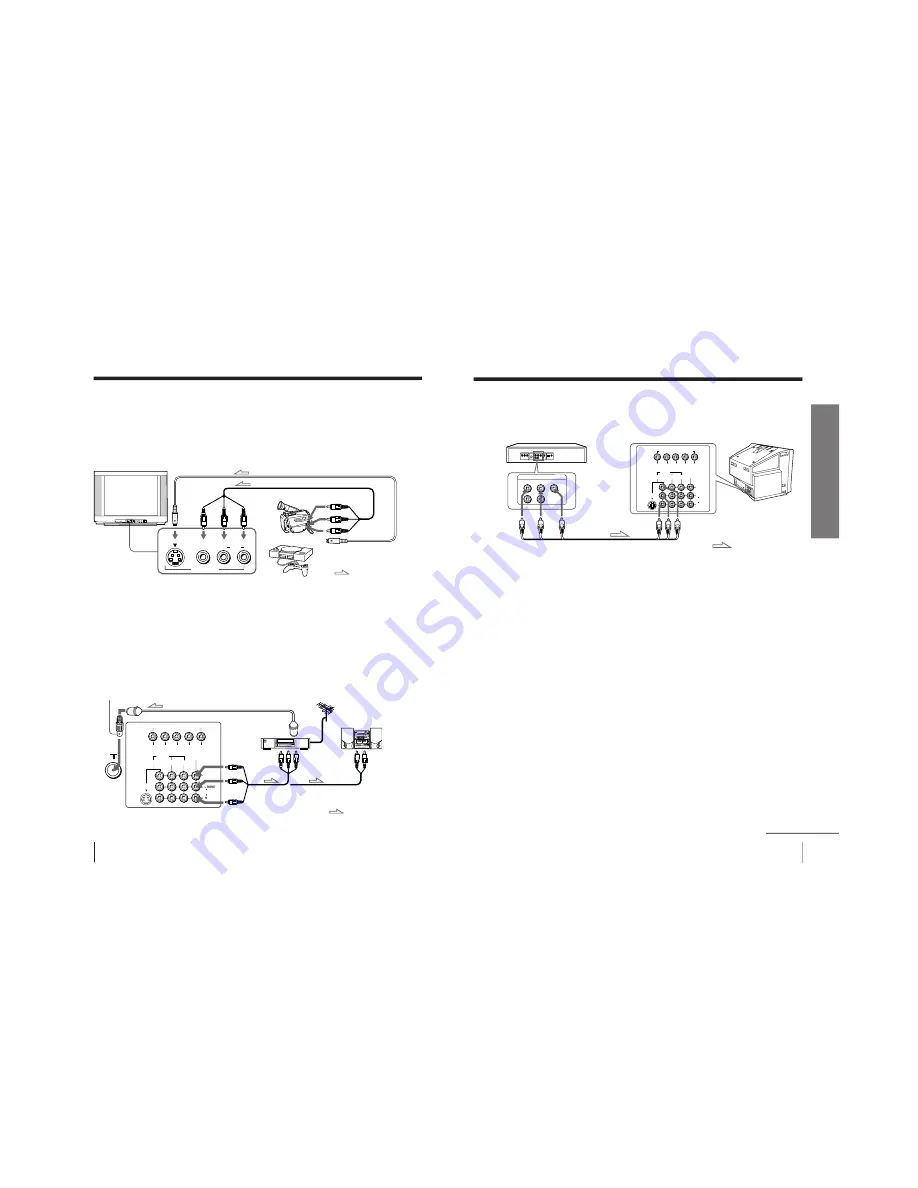
Connecting optional components
You can connect optional audio/video components, such as a VCR, multi disc player,
DVD, camcorder, video game, or stereo system.
To watch the video input from the connected equipment, press VIDEO (see page 12).
Connecting a camcorder/video game equipment using
the VIDEO 3 INPUT jacks
Notes
• When both the S VIDEO input and VIDEO 3 INPUT at the front of your
TV are input at the same time, the S VIDEO input is automatically
selected. To view the video input to VIDEO 3 INPUT, disconnect the S
video cable.
• You can also connect video equipment to the VIDEO IN 1, 2, or 3 jacks at
the rear of your TV.
• Do not connect video equipment to the VIDEO 3 INPUT jacks at the front
and the VIDEO IN 3 jacks at the rear of your TV at the same time;
otherwise the picture will not be displayed properly on the screen.
Connecting audio/video equipment using the
MONITOR OUT jacks
(Not used for this model)
Note
• If you select “DVD” on your TV screen, no signal will be output at the
MONITOR OUT jacks (see page 12).
Antenna adapter (supplied)
7
Using Your New TV
Using Y
our New TV
Connecting a DVD player using the VIDEO IN 1, 2 or 3 jacks
Connect VIDEO IN 1, 2 or 3 AUDIO/VIDEO connectors on your TV to LINE OUT on
your DVD player.
Notes
• Since the high quality pictures on a DVD disc contain a lot of information,
picture noise may appear. In this case, adjust the sharpness (“SHARP”)
under “PERSONAL ADJUST” in the “PICTURE MODE” menu (see
page 21).
• Connect your DVD player directly to your TV. Connecting the DVD
player through other video equipment will cause unwanted picture noise.
continued
DVD player
To VIDEO IN 1, 2 or 3
: Signal flow
Audio/Video cable
(not supplied)
Rear of TV
VIDEO (yellow)
AUDIO-L (MONO) (white)
AUDIO-R (red)
To video and
audio outputs
VIDEO
R-AUDIO-L
LINE OUT
R
L
Y
C
B
C
R
COMPONENT VIDEO(DVD) IN
AUDIO
L (MONO)
R
VIDEO
VIDEO
IN
MONITOR
OUT
1
S VIDEO
2
3


