– 15 –
KLV-32S530A, 26, 32, 37 S550A
RM-GA016
RM-GA016W
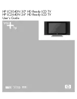
5-2-1. Wire Dressing overview .
5-2-2. Insert Connector Assy 10P and SP Connector Assy 4P
P3
P6
P4-5
P7
P3
P4-5
P8
P6
Non-CISPR model
Left Speaker
1) Insert Connector Assy 10P to HT1 PWB. Attach HT1 PWB
to Light Guide on Bezel.
2) Insert SP Conn Assy 4P to speaker as shown.
Attach Sheet Core, C (X1) as shown.
1) Insert Connector Assy 10P to SW unit. Attach SW unit to Bezel
and dress with Tape (LCD) (X2).
2) Insert SP Conn Assy to speaker and attach Sheet Core, C as shown.
3) Attach Sheet Core, C to Frame Bottom as shown.
Right Speaker
CISPR model
p
Left speaker
Right speaker
Attach Sheet Core, C to SP Conn Assy 4P
and Conn Assy 10P (X1). Use datum line
to position Sheet Core, C. Do not cover
speaker hole with Sheet Core, C.
1
2
1
2
3
Conn Assy 10P (HT1
PWB) behind speaker
Conn Assy 10P (HT1
PWB) behind speaker
Do not cover speaker
hole
Dress Conn Assy 10P
(SW unit) using Tape
(LCD) (X2).
Do not cover speaker hole
Attach Sheet Core, C to SP Conn Assy
4P
and Conn Assy 10P to Frame Bottom
Dress SP Conn Assy 4P and Conn Assy
10P using Sheet Core, C. Use datum line
to position Sheet Core , C.
5-2. KLV-32S530A, 32S550A, 32S550A/L, 32S550A/T