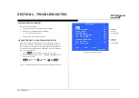
background image

KDL-32R434A 15

Compone nts not ide ntifie d by a part numbe r or de scription 

are  not stocke d be cause  the y are  se ldom re quire d for routine  

se rv ice .

The  compone nt parts of an asse mbly are  indicate d by the  re fe re nce  numbe rs in 

the  far right column of the  parts list and within the  dotte d line s of the  diagram.

NOTE: The  compone nts ide ntifie d by shading and 

!

mark are  critical for safe ty. 

Re place  only with part numbe r spe cifie d. 

NOTE: The  compone nts ide ntifie d by a re d outline  and a   mark contain confide ntial 

information. Spe cific instructions must be  adhe re d to whe ne v e r the se  compone nts are  

re paire d and/or re place d. (Se e  Appe ndix A) 

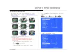
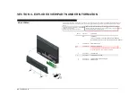
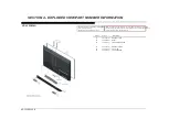
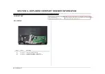
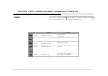
SECTION 4 - EXPLODED VIEW/PART NUMBER INFORMATION

KDL-32R434A

NA 

LCD PANEL

FOR ALL LCD PANEL AND TCON BOARD PART NUMBER

INFORMATION REFER TO THE LCD PANELS SERVICE MANUAL

4-485-012-01 

SIDE JACK COVER

  3 

1-895-502-11 

A BOARD, COMPLETE

AFTER REPLACING THE MAIN BOARD, YOU MUST UPDATE

THE SOFTWARE TO THE LATEST VERSION.

1-492-702-11 

AC ADAPTER

 !   5 

1-848-037-11 

POWER SUPPLY CORD

4-485-011-01 

LOWER COVER (UNDER COVER)

4-479-429-01 

STAND SHAFT 

REF. NO.  

PART NO. 

DESCRIPTION 

4

5

7

2

3

6

1

Summary of Contents for KDL-32R434A

Page 1: ...STORY INFORMATION FOR THE FOLLOWING MANUAL LCD Digital Color TV 9 883 540 01 RB1TK Chassis Segment BA Version Date Subject 1 0 09 19 2013 Original Manual Release Date MODEL COMMANDER DESTINATION KDL 32R434A RM YD093 BRAZIL KDL 32R434A ...

Page 2: ...nking Flowchart 7 No Video Flowchart 8 Video Distortion Flowchart 9 Section 3 Repair Information 10 Repairing the TV 10 Removing the Table Top Stand 10 Removing the Lower Cover 10 Replacing the Main Board 11 Removing the Speakers 14 Removing the Bezel and H Board 14 Section 4 Exploded View Part Number Information 15 KDL 32R434A 15 Connectors 17 Screws 18 Section 5 Accessories Part Number Informati...

Page 3: ... the Inverter Boards is prohibited CAUTIONS AND WARNINGS SAFETY CHECK OUT After correcting the original service problem perform the following safety checks before releasing the set to the customer 1 Check the area of your repair for unsoldered or poorly soldered connections Check the entire board surface for solder splashes and bridges 2 Check the interboard wiring to ensure that no wires are pinc...

Page 4: ...ters must have an accurate low voltage scale Nearly all battery operated digital multimeters that have a 2 VAC range are suitable see Figure A To Exposed Metal Parts on Set 0 15 µF Earth Ground AC Voltmeter 0 75V Figure A Use an AC voltmeter to check AC leakage HOW TO FIND A GOOD EARTH GROUND The cover plate retaining screw on most AC outlet boxes is at earth ground Verify the AC outlet box retain...

Page 5: ...hms Distorção Harmônica Total 127 V CA THD 10 sinal 1 KHz Alto falante de 8 Ohms Nível de entrada 500 mVrms SECTION 1 SPECIFICATIONS AND LAYOUTS Nome do modelo KDL 32R434A Energia e outros Requisito de energia 110 220 V CA 60 Hz Consumo de energia 61 W em uso em modo de espera Menos do que 1 W Tamanho da tela Aprox 80 0 polegadas medidas diagonalmente 31 5 Classe 32 linhas vertical 8 6 7 pontos ho...

Page 6: ...KDL 32R434A 2 SECTION 1 SPECIFICATIONS AND LAYOUTS BOARD LAYOUT KDL 32R434A TCON H BOARD MAIN BOARD A BOARD SIDE JACK COVER ...

Page 7: ...KDL 32R434A 3 SECTION 1 SPECIFICATIONS AND LAYOUTS WIRE DRESSING KDL 32R434A KDL 32R434A ...

Page 8: ...what is causing the television to shut down If the screen displays a 0 no error has occurred 1 Press POWER to turn on the TV and then turn it off again 2 Press the following buttons on the Remote Commander within 1 second of each other DISPLAY Channel 5 Volume POWER NOTE This differs from accessing Service Adjustments Mode Volume SECTION 2 TROUBLESHOOTING Self Diagnosis Supported model Back 002 MA...

Page 9: ...om the chart Blue Triangle Secondary Possible defective part 3 Bring the primary component listed for that symptom 5 Chart Color Code Power Audio 2X 3X 6X Dead set No Video Whole Screen Distortion Isolated Area Distortion No Audio MAIN BOARD LCD PANEL TCON Video Protection Modes 4 Follow the associated flowcharts in the Training Manual to isolate the board Board NOTE REFER TO LCD PANEL SERVICE MAN...

Page 10: ...AGRAMS OVERALL BLOCK DIAGRAM COMPONENT COMPOSITE RF COMPOSITE AUDIO L R IN AC ADAPTER LED IR RX LCD PANEL TCON LED BACKLIGHTS A H L R AUDIO OUT MT5580 A V DECODER A V PROCESS TUNER USB HDMI 1 LVDS AC IN CLASS D AUDIO AMP MAIN BOARD CONTROL KEYS CABLE ANTENNA ...

Page 11: ...ING FLOWCHART Protect Shutdown Standby LED Blinking No Yes Yes Yes 2X Main Board 3X No 6X SONY logo appears before shutdown Yes No LCD Panel AC Adapter AC Adapter For Part Number information refer to Section 4 Exploded View Part Number Information on page 15 ...

Page 12: ... LVDS connector at TCON while unit is running This may need to be done more than once Any flashes seen on screen Yes No Any OSD graphics present No Main Board No LCD Panel Yes Yes Main Board LCD Panel For Part Number information refer to Section 4 Exploded View Part Number Information on page 15 ...

Page 13: ... Video Distortion Is distortion across entire screen Any horizontal lines No No Yes Yes Improper of missing colors Yes Main Board No Vertical lines or bars No Yes Lines move when wide mode changed Yes No LCD Panel Main Board LCD Panel Any single or isolated vertical lines Yes LCD Panel More than 1 vertical band No Yes LCD Panel Uneven brightness LCD Panel Yes No ...

Page 14: ...m the required service adjustments and checks 5 Verify the repair resolved the issue REMOVING THE TABLE TOP STAND 1 Place TV face down on a soft and flat surface 2 Remove 2 screws from Table Top Stand and carefully detach from Lower Cover REMOVING THE LOWER COVER 1 Locate and disconnect AC Power Cord 2 Locate and remove all screws from the Lower Cover 3 Grasp the areas shown on the Lower Cover to ...

Page 15: ... the TV b Press POWER to turn on the TV c Wait until the Software update is complete and TV turns OFF 6 Access Service Mode by pressing the following buttons within 1 second of each other DISPLAY Channel 5 Volume POWER Sound Adjustment Wide Band Tuning Range Scan Self diagnosis history Status Information LVDS Spectrum 0 30 Low of HPD 5 TVD_MCDONE_CNT 20 Demo Special Bypass AVI Info Detect On Panel...

Page 16: ...de 11 Press to be able to select the first digit Sound Adjustment Wide Band Tuning Range Scan Self diagnosis history Status Information LVDS Spectrum 0 30 Low of HPD 5 TVD_MCDONE_CNT 20 Demo Special Bypass AVI Info Detect On Panel Selection 192_TPT315B5 XVN03 UART Selection No Log SERIAL NUMBER EDIT _ _ _ _ _ _ _ MODEL NAME EDIT Set Home Exit Service Mode 12 Press or to select numbers and then to ...

Page 17: ...elf diagnosis history Status Information LVDS Spectrum 0 30 Low of HPD 5 TVD_MCDONE_CNT 20 Demo Special Bypass AVI Info Detect On Panel Selection 192_TPT315B5 XVN03 UART Selection No Log SERIAL NUMBER EDIT 8500001 MODEL NAME EDIT _ _ _ _ _ _ _ _ _ _ _ Set Home Exit Service Mode 17 Press or to select characters and then to move to the next space until Model Name is complete NOTE Make sure to includ...

Page 18: ... REMOVING THE SPEAKERS 1 Lift and remove Speakers then disconnect connectors to detach 2 Locate and remove 2 screws from Speaker Cover Twist downwards to release clips from the Bezel REMOVING THE BEZEL AND H BOARD 1 Use a small and narrow tool to release H Board from Bezel 2 Disconnect the connector from the H Board to detach 3 Place the TV face up then grasp the Bezel carefully on the shown areas...

Page 19: ... a red outline and a mark contain confidential information Specific instructions must be adhered to whenever these components are repaired and or replaced See Appendix A SECTION 4 EXPLODED VIEW PART NUMBER INFORMATION KDL 32R434A 1 NA LCD PANEL FOR ALL LCD PANEL AND TCON BOARD PART NUMBER INFORMATION REFER TO THE LCD PANELS SERVICE MANUAL 2 4 485 012 01 SIDE JACK COVER 3 1 895 502 11 A BOARD COMPL...

Page 20: ... information Specific instructions must be adhered to whenever these components are repaired and or replaced See Appendix A KDL 32R434A 56 56 52 Bracket MB Btm Bracket MB Top 53 54 55 51 51 REF NO PART NO DESCRIPTION 51 4 470 954 01 BRACKET VESA 52 4 485 009 01 BEZEL 53 1 895 413 11 H BOARD MOUNTED 54 4 470 953 01 BRACKET STAND 55 4 485 010 01 SP COVER 56 1 858 956 11 LOUD SPEAKER Reinstall Bracke...

Page 21: ...onents identified by a red outline and a mark contain confidential information Specific instructions must be adhered to whenever these components are repaired and or replaced See Appendix A 101 1 910 109 12 LVDS CABLE 32 MB TCON 30P 102 1 910 109 11 CONNECTOR ASSEMBLY 32 MB IR 6P 103 1 910 109 10 CONNECTOR ASSEMBLY 32 MB SP LR 4P REF NO PART NO DESCRIPTION CONNECTORS 101 102 103 KDL 32R434A ...

Page 22: ... repaired and or replaced See Appendix A SCREWS Lower Cover 2 SCREW BVTP 4X16 TYPE2 IT 3 SCREW BVTP 4X10 TYPE2 IT 3 SCREW BVTP 3X8 TYPE2 IT 3 SCREW M5X18 SW IRST 2 580 640 01 7 685 660 79 7 685 646 79 P N DESCRIPTION KDL 32R434A Stand Bracket 4 2 580 638 01 MB Bracket Top 2 MB Bracket Bottom 2 SCREW BVTP2 4X8 Speaker Cover 2 4 466 880 01 4 466 881 01 SCREW M3X10 SW FANT Table Top Stand to TV 2 Low...

Page 23: ... you use the screws provided with the TV CAUTION These screws cannot be used to secure the TV to the Wall Mount Brackets 4 476 481 41 MANUAL INSTRUCTION 4 476 482 41 GUIDE QUICK SET UP 4 262 708 04 CLAMPER CABLE OPTIONAL ACCESSORIES PART NO DESCRIPTION 4 414 470 01 SUPPORT BELT KIT REMOTE COMMANDER PART NO DESCRIPTION 1 492 066 21 REMOTE COMMANDER RM YD093 SECTION 5 ACCESSORIES PART NUMBER INFORMA...

Page 24: ...ey components shall be identified with a red outline and a 2 Only repair boards or components listed in the service manual shall be utilized for replacement and or repair 3 Disassembly decryption or reverse engineering component s is strictly prohibited 4 Any board in which the Servicer replaces an encryption key component must be placed back into the set it orignally came from and the replaced de...

Reviews: