background image

- 14 -

4-1.  BLOCK DIAGRAM

MAIN CHIP

PNX8543M2

Aerial/Cable

PC Audio
SCART1
SCART2

Line Out

Opt. Out

Component

USB

C

I

C

I

PC

BEN

HDMI1
HDMI2
HDMI3

HDMI4

HDMI

EQ/SW/EDID

TDA19997

HP Out

CV-Side

NVM

Key

IR

32,26,22

WXGA CCFL

46,40,37,32

FHD CCFL

DDR2

512Mb

DDR2

512Mb

Si-TU

SUT_AE102T

Demodulator

CXD2817R-T4

DVB-T/C

AUDIO

Buffer

CXA3813N

NAND FLASH

NAND01G

W3B2CN6F

AUDIO

D-Amp

TPA3110D2

Light 

Sensor

BH1690FVC

Control Button

HLR

PANEL

Power Supply

Gxx

LED

3a-2/5-0

5-2

H2LS

www.freeservicemanuals.info

1/20/2019

Digitized in Heiloo the Netherlands

Not for  sale!

Summary of Contents for KDL-32BX400

Page 1: ...e Date Part Number Description of Revisions Version 2010 01 9 883 479 01 Original Manual 1 0 2010 10 9 883 479 02 How to reset OSD Menu errors P8 2 0 2010 12 9 883 479 03 Add Screw Part Number Base Stand P18 3 0 www freeservicemanuals info 1 20 2019 Digitized in Heiloo the Netherlands Not for sale ...

Page 2: ... SERVICE MANUAL AZ1 N 5 2 CHASSIS MODEL DEST RM ED022 KDL 32BX400 AEP UK KDL 40BX400 AEP UK MODEL DEST www freeservicemanuals info 1 20 2019 Digitized in Heiloo the Netherlands Not for sale ...

Page 3: ...n 12 3 2 5 Factory Reset 12 3 3 TT Mode 13 4 DIAGRAMS 4 1 Block Diagram 14 4 2 Circuit Board Location 15 5 EXPLODED VIEWS 5 1 Chassis 16 5 2 Bezel Assy Stand Assy 18 5 3 Rear Cover Assy Power Supply Cords 19 6 PARTS LIST 20 SAFETY RELATED COMPONENT WARNING COMPONENTS IDENTIFIED BY SHADING AND MARKED ON THE EXPLODED VIEWS AND IN THE PARTS LIST ARE CRITICAL FOR SAFE OPERATION REPLACE THESE COMPONENT...

Page 4: ...ON 1 GENERAL How to replace the fuse Open the fuse compartment with a screwdriver blade and replace the fuse FUSE WARNING UK Models only The flexible mains lead is supplied connected to a B S 1363 fused plug having a fuse of the correct rating for the set Should the fuse need to be replaced use a fuse of the same rating approved by ASTA to BS 1362 ie one that carries the need to be replaced use a ...

Page 5: ... Vp p 75 ohms COMPONENT IN Audio input phono jacks HDMI IN 1 2 3 4 Video 1080p 1080p24 1080i 720p 576p 576i 480p 480i Audio Two channel linear PCM 32 44 1 and 48 kHz 16 20 and 24 bits Dolby Digital PC see page 6 Analogue audio minijack HDMI 1 only AV3 Video input phono jack AV3 Audio input phono jacks DIGITAL AUDIO OUT OPTICAL Digital optical jack Two channel linear PCM Dolby Digital Audio output ...

Page 6: ...9 x 25 1 cm 82 5 x 55 4 x 26 0 cm KDL 32NX5xx 80 4 x 53 2 x 22 0 cm KDL 32BX3 BX4xx 80 0 x 53 2 x 22 0 cm KDL 32EX3 EX4xx 67 2 x 45 9 x 22 0 cm 55 1 x 40 2 x 21 5 cm without stand 112 7 x 67 4 x 10 2 cm 102 3 x 62 8 x 10 0 cm KDL 40NX5xx 99 6 x 59 8 x 9 9 cm KDL 40BX4xx 99 2x59 8x10 0 cm KDL 40EX4xx 92 1 x 56 4 x 9 8 cm 82 5 x 51 7 x 10 2 cm KDL 32NX5xx 80 4x49 7x9 6cm KDL 32BX3 BX4xx 80 0x49 7x9 ...

Page 7: ... VGA SVGA 800 600 37 9 60 VESA Guidelines XGA 1024 768 48 4 60 VESA Guidelines WXGA 1280 768 47 4 60 VESA WXGA 1280 768 47 8 60 VESA WXGA 1360 768 47 7 60 VESA SXGA 1280 1024 64 60 VESA UXGA 1600 1200 75 60 VESA HDTV 1920 1080 67 5 60 EIA Signals Horizontal Pixel Vertical Line Horizontal frequency kHz Vertical frequency Hz Standard VGA 640 480 31 5 60 VGA SVGA 800 600 37 9 60 VESA Guidelines XGA 1...

Page 8: ...round Video Input 19 Video Output 1V 3dB positive sync 0 3V 3 10dB 20 Video Input 1V 3dB positive sync 0 3V 3 10dB Video Input Y S Signal 1V 3dB positive sync 0 3V 3 10dB 21 Common Ground Shield 1 3 5 7 9 11 13 15 17 19 21 2 4 6 8 10 12 14 16 18 20 19 17 15 13 11 9 7 5 3 1 18 16 14 12 10 8 6 4 2 5 4 3 2 1 10 9 8 7 6 15 14 13 12 11 Pin No Signal Assignment Pin No Signal Assignment Pin No Signal Ass...

Page 9: ...ode Goes into standby 05 Panel Error Panel ID error In normal and factory mode Goes into standby 06 Inverter error In normal and factory mode Goes into standby 13 NVM error In initialisation state Adds error to error menu 14 I2C error In normal and factory mode Adds error to error menu 15 Tuner error In initialisation state Adds error to error menu 16 DVB T C Demod error In initialisation state Ad...

Page 10: ...ove the 4 stand fixing screws indicated and lift the TV set up and away from the Stand Assy Screw Part number s and Description s 2 580 608 01 SCREW PSW M5X16 2 4 Loudspeaker Removal 2 3 Speaker Bracket Removal To remove the Loudspeaker first disconnect the loudspeaker connectors and then remove the 2 screws circled Finally gently pull the Loudspeaker out of the speaker bracket Screws To remove th...

Page 11: ...ews Screw Part number s and Description s 2 580 592 01 SCREW PSW M3X8 To remove the BEN board disconnect all connectors and then remove the 4 screws circled and ease the board gently away from the back of the TV set To remove the H2LS board disconnect the 1 connector and release the 3 clips circled and ease the board gently away from the TV set Clips Screw Screw Part number s and Description s 2 5...

Page 12: ...ccessing the Service Menu switch the TV set OFF and then ON again 3 2 1 Service General Menu The following menu appears on the screen when you enter the Service General Menu See Pic 2 This menu allows you to view the product information set the TV into Aging Mode and perform Software Upgrade to the TV set 3 2 2 White Balance Adjustment The following menu appears on the screen when you enter the Wh...

Page 13: ...ction of Factory Reset See Pic 6 allows the TV to be reset to factory shipping condition This will restore all settings to those which were contained in the TV on first shipment DVB Detail Panel Backlight Sound Status OSD Service Menu DVB Basic Start Now White Balance Adjustment OSD Service Menu Country Selection Factory Reset Factory Service Menu Store Exit Service General Menu Open Ireland Close...

Page 14: ...e to 35 04 Set volume to 50 05 Set volume to 65 06 Set volume to 80 07 Ageing mode on 08 Shipping Condition 09 WB Levels Check 11 Panel_id A 12 Panel_id B 15 Speaker_id A 16 Speaker_id B 19 Factory toggle mode ON OFF 27 CBA mode toggle ON OFF 31 ECS mode toggle ON OFF 32 Set DVB T channel table 33 Set DVB C channel table 36 Full HD HDMI EDID Write 37 WXGA HDMI EDID Write 41 Re initialise NVM 43 Se...

Page 15: ... CV Side NVM Key IR 32 26 22 WXGA CCFL 46 40 37 32 FHD CCFL DDR2 512Mb DDR2 512Mb Si TU SUT_AE102T Demodulator CXD2817R T4 㧔DVB T C㧕 AUDIO Buffer CXA3813N NAND FLASH NAND01G W3B2CN6F AUDIO D Amp TPA3110D2 Light Sensor BH1690FVC Control Button HLR PANEL Power Supply Gxx LED 3a 2 5 0 5 2 H2LS www freeservicemanuals info 1 20 2019 Digitized in Heiloo the Netherlands Not for sale ...

Page 16: ... METAL FILM RC SOLID FPRD NON FLAMMABLE CARBON FUSE NON FLAMMABLE FUSIBLE RS NON FLAMMABLE METAL OXIDE RB NON FLAMMABLE CEMENT RW NON FLAMMABLE WIREWOUND ADJUSTMENT RESISTOR COIL LF 8L MICRO INDUCTOR CAPACITOR TA TANTALUM PS STYROL PP POLYPROPYLENE PT MYLAR MPS METALIZED POLYESTER MPP METALIZED POLYPROPYLENE ALB BIPOLAR ALT HIGH TEMPERATURE ALR HIGH RIPPLE Les composants identifiés par une trame e...

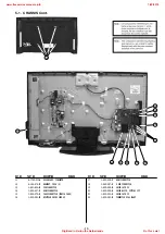
Page 17: ...STATIC CONVERTER TV 32 inches 1 474 201 21 STATIC CONVERTER TV 40 inches 3 A 1763 564 A BEN BOARD COMPLETE 4 4 166 268 22 BRACKET SIDE JACK 5 8 597 735 00 UNIVERSAL SIL TU SUT AE102T 6 1 858 364 11 LOUDSPEAKER 4 5x12 5cm 7 4 164 507 01 BRACKET SP 32L 32 inches 4 166 119 11 BRACKET SP 40L 40 inches 8 A 1763 559 A HLR BOARD COMPLETE 9 4 164 509 02 COVER UNDER 32 32 inches 4 166 123 11 COVER UNDER 37...

Page 18: ... 17 1 822 638 11 HDMI CONNECTOR 18 1 842 087 11 D SUB CONNECTOR 19 1 822 524 31 PHONO JACK 2P 20 1 822 954 11 PHONO BLOCK OPTICAL OUT 21 1 822 523 11 PHONO JACK 5P 22 1 822 580 21 CONNECTOR DUAL SCART 5 1 CHASSIS Cont REF NO PART NO DESCRIPTION REMARK REF NO PART NO DESCRIPTION REMARK 17 11 12 13 14 15 16 18 19 20 21 22 17 www freeservicemanuals info 1 20 2019 Digitized in Heiloo the Netherlands N...

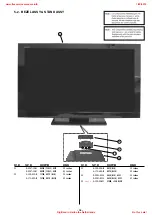
Page 19: ...40 inches 52 4 158 400 11 COVER NECK M3B 32 inches 4 171 690 01 COVER NECK ML3B 40 inches 53 4 158 354 01 NECK M3B 32 inches 4 171 686 01 NECK ML3B 40 inches 54 X 2541 850 1 BASE M3B ASSY 32 inches X 2541 851 1 BASE ML3B ASSY 40 inches 55 Ver 3 0 4 159 298 01 SCREW PSW M4X10 52 53 54 55 www freeservicemanuals info 1 20 2019 Digitized in Heiloo the Netherlands Not for sale ...

Page 20: ...101 X 2547 155 1 REAR COVER CON32 ASSY 32 inches X 2547 124 1 REAR COVER CON40 ASSY 40 inches 102 3 106 546 51 ECS COVER 103 1 837 454 11 POWER SUPPLY CORD AEP 32 40 inches 104 1 837 455 11 POWER SUPPLY CORD UK 32 40 inches 101 103 104 102 www freeservicemanuals info 1 20 2019 Digitized in Heiloo the Netherlands Not for sale ...

Page 21: ...items 20 Page ACCESSORIES AND CONNECTORS 21 REMOTE COMMANDER 21 Note To ensure safety and reliability it is Sony policy that boards should not be repaired in the field as a result all boards are regarded as non service items for exchange only and are not indicated in the parts list of this service manual www freeservicemanuals info 1 20 2019 Digitized in Heiloo the Netherlands Not for sale ...

Page 22: ...910 060 80 CONNECTOR ASSY 15P G2M CN6401 BEN CN6006 1 910 060 83 MULTI HARNESS SPEAKER BEN CN6007 7901 HLR H2LS SPEAKERS 1 910 060 84 CONNECTOR ASSY 14P G2M CN6402 INVERTER INSTRUCTION MANUALS 4 168 148 11 INSTRUCTION MANUAL UK ENGLISH 4 168 148 21 INSTRUCTION MANUAL AEP GERMAN SPANISH FRENCH ITALIAN DUTCH PORTUGUESE 4 168 148 31 INSTRUCTION MANUAL AEP BULGARIAN CZECH DANISH FINNISH GREEK HUNGARIA...

Page 23: ...9 883 479 03 Sony Corporation Sony UK Service Promotions Dept English 10LP7100 1 Printed in U K 2010 12 www freeservicemanuals info 1 20 2019 Digitized in Heiloo the Netherlands Not for sale ...

Reviews: