222
Location and Function of Parts and Controls
Location and
Function of Parts
and Controls
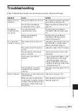
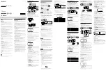
Front
a
?
/
1
(power) switch
Turns on/off the system.
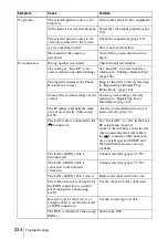
b
?
/
1
(power) indicator
Starts blinking in green when the power
switch is pressed to on, then lights in
green. Lights in orange when the system
is set to standby mode.
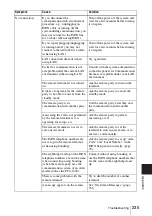
c
LAN 1 ALERT indicator
When the system is connected to LAN
via the
1 connector on the rear, this
indicator lights in yellow when packet
error (loss) or link error occurs during
communication.
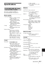
d
LAN 2 ALERT indicator
When the system is connected to LAN
via the
2 connector on the rear, this
indicator lights in yellow when packet
error (loss) or link error occurs during
communication.
e
Communication status indicator
Lights in white for several seconds then
goes out when the system starts.
Blinks while dialing or receiving a call,
and the indicator stays lit during
communication.
f
TABLET connector
Connect to a pen tablet (not supplied) for
annotation, or the Key Module (not
supplied) for software installation.
g
Memory Stick slot
Insert a “Memory Stick” (not supplied)
into this slot.
A “Memory Stick Duo” can also be
inserted.
h
VIDEO IN YPbPr (component
input) jacks (phono jack)
Connect to the component (YPbPr)
signal outputs of the optional camera or
external video equipment.
i
AUDIO 2 IN L/R jacks (phono jack)
Connect to the audio outputs of the
optional camera or audio equipment.
j
MAINTENANCE connector (D-sub
9-pin)
Used for maintenance service.
Appendix
PCS-XG80S HD Visual
Communication System
OPEN
LAN 1 ALERT
LAN 2 ALERT
/
OPEN
VIDEO IN
AUDIO 2 IN
MAINTENANCE
Y
Pb
Pr
L
R
1 234
5
6
7
8
9
q;
Summary of Contents for Ipela PCS-XG80
Page 266: ...Sony Corporation ...


