background image

5-6

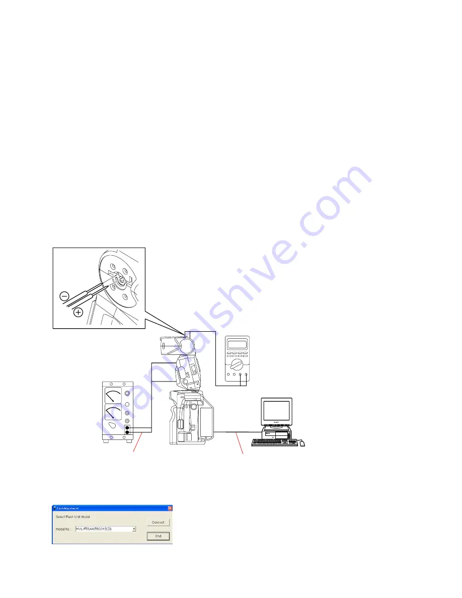
HVL-F56AM

Personal Computer

Digital multimeter

Power supply adaptor

USB cord with connector

DC power supply

(5.8 V, 1.8 A)

The probe (-) of the digital multimeter can be connected
to the negative line of the DC power supply.
Ensure the bounce angle is 0 degree (locked position).

Camera

5-3.

CHARGING VOLTAGE ADJUSTMENT

Note:

If dialog box of error code appears during the adjustment, check the reason of error referring to page 5-20.

Equipment

• Personal Computer (PC)

• Camera DSLR-A100

• USB Cord With Connector

• Flash Adjustment Program

Note:

Flash Adjustment Program is downloadable from the ESI homepage.

• DC Power Supply

• Digital Multimeter

• Power Supply Adaptor

1. Preparations

1)

Set the equipments as shown in the Fig. 5-3-1.

Note:

For connection method of power supply adaptor, refer to page  5-2.

Set the detection pin of the digital multimeter to the DC voltage detecting point.

(The probe (-) of the digital multimeter can be connected to the negative line of the DC power supply.)

Fig. 5-3-1

2)

Set the voltage and current of the DC power supply to “5.8V, 1.8A”.

3)

Start the flash adjustment program “FlashAdjustment.exe” referring to “5-1-3. Flash Adjustment Program”.

Fig. 5-3-2

Summary of Contents for HVL-F56AM

Page 1: ...How to use Acrobat Reader Sony EMCS Co HVL F56AM SERVICE NOTE SPECIFICATIONS FRAME SCHEMATIC DIAGRAM DISASSEMBLY REPAIR PARTS LIST ADJUSTMENTS HVL F56AM Ver 1 0 2006 06 FLASH 2006F0800 1 2006 06 Published by Kohda TEC 9 852 122 11 US Model Canadian Model AEP Model Chinese Model E Model ...

Page 2: ...250 6 7 12 13 15 17 19 22 1 500 4 5 8 6 9 5 10 12 13 16 1 1000 3 5 6 6 7 7 5 9 9 5 11 1 2000 2 4 4 3 4 5 5 6 6 7 8 1 4000 1 7 3 3 5 3 7 4 5 4 7 5 6 1 8000 1 2 2 1 2 4 2 5 3 3 5 4 1 12000 1 1 8 2 2 1 2 5 2 8 3 5 Frequency Repetition Alkaline Lithium Nickel hydride 1550 mAh Frequency sec 0 2 11 0 2 13 0 2 8 Repetition times 90 3200 250 8000 80 2800 Repetition is the approximate number of times that ...

Page 3: ...ic Diagram 3 1 4 REPAIR PARTS LIST 4 1 Exploded Views 4 1 4 2 Supplied Accessories 4 5 5 ADJUSTMENTS 5 1 Preparations 5 1 5 2 Initialization of EEPROM Writing of Initial Value 5 4 5 3 Charging Voltage Adjustment 5 6 5 4 Full charge Voltage Stop Charge Voltage Check 5 8 5 5 Home Position Adjustment 5 9 5 6 Power Level Check Adjustment 5 11 5 7 Flat Flash Intensity Check Adjustment 5 13 5 8 Assist M...

Page 4: ...on t use paint thinner ketone nor alcohol Insert the specific screws vertically to the part when installing a exterior part Be careful not to tighten screws too much 1 3 Unleaded Solder This unit uses unleaded solder Boards requiring use of unleaded solder are printed with the lead free mark LF indicating the solder contains no lead Caution Some printed circuit boards may not come printed with the...

Page 5: ...Board Repairing Keep the temperature of the soldering iron around 270 C during repairing Do not touch the soldering iron on the same conductor of the circuit board within 3 times Be careful not to apply force on the conductor when soldering or unsoldering SAFETY RELATED COMPONENT WARNING COMPONENTS IDENTIFIED BY MARK 0 OR DOTTED LINEWITH MARK 0 ON THE SCHEMATIC DIAGRAMS AND IN THE PARTS LIST ARE C...

Page 6: ...OARD SET D The charging capacitor of the PC board set D is charged up to the maximum 330 V potential There is a danger of electric shock by this high voltage when the capacitor is handled by hand The electric shock is caused by the charged voltage which is kept without discharging when the main power of the unit is simply turned off Therefore the remaining voltage must be discharged as described b...

Page 7: ... DISASSEMBLY 2 1 1 SHOE FOOT UNIT AND COVER SET 1 Shoe Foot Unit 2 Cover E Set 5 Power Case Unit 3 Battery Case Lid Set 4 Plastic Sheet 7 Flash Block 6 Cover F Set See Page 2 3 HELP01 HELP02 HELP03 EXPLODED VIEW A B A B ...

Page 8: ...D A B 1 Cover B Set 2 Disk 6 PC Board Set D 5 Motor Unit 4 Cover A Set 3 Cover D 7 Cover C Set EXPLODED VIEW HELP04 HELP04 HELP06 HELP07 HELP05 Refer to page 2 1 Discharging of the charging capacitor on the PC board set D when discharging the capacitor ...

Page 9: ...ELP HELP Apply the grease G 85 Apply the grease G 85 Note for assembling and grease applying positions are shown HELP01 Apply the grease G 85 to the instruction part as shown in the figure Grease G 85 J 6082 626 A ...

Page 10: ...instruction part as shown in the figure Grease G 85 J 6082 626 A HELP03 Apply the grease G 85 to the instruction part as shown in the figure Grease G 85 J 6082 626 A Apply the grease G 85 Apply the grease G 85 Apply the grease G 85 Apply the grease G 85 ...

Page 11: ...e Grease G 85 J 6082 626 A HELP05 Apply the contact treatment grease F 20 to the instruction part as shown in the figure Contact treatment grease F 20 J 6082 629 A HELP06 Apply the grease G 85 to the instruction part as shown in the figure Grease G 85 J 6082 626 A Apply the grease G 85 Apply the grease G 85 Apply the grease G 85 ...

Page 12: ...HVL F56AM HELP HELP07 Apply the grease G 85 to the instruction part as shown in the figure Grease G 85 J 6082 626 A Apply the grease G 85 ...

Page 13: ... 2 2 2 2 2 5 6 PINK 6 8 9 7 7 5 2 4 2 3 3 0 9 4 3 4 3 4 5 9 7 3 4 2 1 Motor Unit bottom view Motor Unit side view Abbreviation number of the wire color Motor Unit Cover F Set Cover A Set Cover E Set Power Case Unit Cover E Set Shoe Foot Unit Cover C Set PC Board Set D PC Board Set W XE Tube AF Assist Light Unit 3 FRAME SCHEMATIC DIAGRAM 3 1 FRAME SCHEMATIC DIAGRAM ...

Page 14: ...hey may have some difference from the original one Items marked are not stocked since they are seldom required for routine service Some delay should be anticipated when ordering these items The mechanical parts with no reference number in the exploded views are not supplied 4 2 693 229 01 SCREW TAPPING M2 0X6 0 5 X 2148 449 1 FOOT UNIT SHOE 6 2 693 228 01 SCREW K M2 0X4 0 Ref No Part No Descriptio...

Page 15: ... SET D 62 2 693 288 01 SCREW TAPPING M2 0X5 0 63 2 693 280 01 DISK Ref No Part No Description 64 2 693 236 01 CLICK 65 2 693 235 01 CLICK SP 66 2 693 277 01 SHAFT B BOUNCE 67 X 2148 451 1 COVER C SET 68 2 693 285 01 SCREW K M1 4X1 8 69 2 693 234 01 COVER D 70 2 693 283 01 RUBBER B SIDE 71 2 580 751 01 SHEET POLYIMIDE Note 72 2 693 281 01 PLATE LOCK 73 2 693 279 01 PLATE SP LOCK 74 X 2148 453 1 SHA...

Page 16: ... SET Ref No Part No Description 101 X 2148 458 1 COVER E SET 102 2 693 289 01 PANEL AF ASSIST LIGHT 103 X 2148 459 1 LIGHT UNIT AF ASSIST 104 2 693 290 01 SCREW TAPPING M2 0X5 0 105 X 2148 460 1 PC BOARD SET W 101 103 105 104 102 ...

Page 17: ...4 4 HVL F56AM 4 1 4 COVER F SET Ref No Part No Description 151 X 2148 461 1 COVER F SET 152 2 693 291 01 LABEL 151 152 ...

Page 18: ...S CND 2 687 455 11 MANUAL INSTRUCTION ENGLISH FRENCH GERMAN ITALIAN DUTCH AEP 2 687 455 21 MANUAL INSTRUCTION ENGLISH PORTUGUESE SPANISH SWEDISH RUSSIAN AEP 2 687 455 31 MANUAL INSTRUCTION ENGLISH ARABIC TRADITIONAL CHINESE SIMPLIFIED CHINESE KOREAN E CH Abbreviation CH Chinese model CND Canadian model Case 2 691 858 01 Mini stand 2 691 857 01 ...

Page 19: ... ADJUSTMENT 5 4 FULL CHARGE VOLTAGE STOP CHARGE VOLTAGE CHECK 5 5 HOME POSITION ADJUSTMENT 5 6 POWER LEVEL CHECK ADJUSTMENT 5 7 FLAT FLASH INTENSITY CHECK ADJUSTMENT 5 8 4 LCD LED Displays Check When replacing the PC board set D or power case unit 5 3 CHARGING VOLTAGE ADJUSTMENT 5 4 FULL CHARGE VOLTAGE STOP CHARGE VOLTAGE CHECK 5 5 HOME POSITION ADJUSTMENT 5 6 POWER LEVEL CHECK ADJUSTMENT 5 7 FLAT...

Page 20: ...0 M Byte or more recommended Hard disk free area 15 M Byte or more recommended USB terminal Standard equipment Graphics 32 000 colors or more recommended VGA monitor Note 2 Attach the power supply adaptor as shown in Fig 5 1 2 Fig 5 1 2 Personal computer Note 1 Back ground paper J 2501 130 A USB cord with connector 1 833 062 11 Power supply adaptor J 6082 602 A Note 2 J 1 J 2 J 4 J 5 J 3 AE master...

Page 21: ...Preparing the DSLR A100 adjustment program described on the top cover of the camera DSLR A100 service manual 9 852 130 51 2 Start the Flash Adjustment Program 1 Connect the flash to the camera 2 Turn the POWER switch of the camera to OFF then connect the camera and PC with the USB cord with connector 3 Set the mode dial of camera to M 4 Turn the POWER switch to ON while pressing the shutter button...

Page 22: ... Preparations 1 Connect the checking flash to the camera 2 Start the flash adjustment program FlashAdjustment exe referring to 5 1 3 Flash Adjustment Program Fig 5 2 1 2 Initializing Method 1 Select the HVL F56AM 5600HS D from the pull down menu of the flash adjustment program then click the Connect button Note Click the End button to terminate the flash adjustment program 2 When checking message ...

Page 23: ...nt to initialize EEPROM appears click the Yes button 6 When completion message Done appears after initialization click the OK button Fig 5 2 4 7 When the initialization is completed click the Exit button to go back the adjustment menu 8 Perform the 5 3 CHARGING VOLTAGE ADJUSTMENT continuesly ...

Page 24: ...0 USB Cord With Connector Flash Adjustment Program Note Flash Adjustment Program is downloadable from the ESI homepage DC Power Supply Digital Multimeter Power Supply Adaptor 1 Preparations 1 Set the equipments as shown in the Fig 5 3 1 Note For connection method of power supply adaptor refer to page 5 2 Set the detection pin of the digital multimeter to the DC voltage detecting point The probe of...

Page 25: ...push the test flash button to fire the flash 5 Click the 250V Adj button of the adjustment menu when the voltage indicated on the digital multimeter reaches 250 V 6 Change the current output of the DC power supply to 0 5 A to slow down the charging speed 7 Click the 305V Adj button of the adjustment menu when the voltage indicated on the digital multimeter reaches 305 V 8 Click the 330V Adj button...

Page 26: ...ll charge push the test flash button to fire the flash 3 When the voltage indicated on the digital multimeter is over to 200V change the current output of the DC power supply to 0 5 A to slow down the charging speed 4 Check that the following specification is satisfied during charge Specification When the voltage indicated on the digital multimeter reaches 305 0 5 V the flash ready lamp will light...

Page 27: ...ng to page 5 20 Equipment Personal Computer PC Camera DSLR A100 USB Cord With Connector Flash Adjustment Program Note Flash Adjustment Program is downloadable from the ESI homepage DC Power Supply Digital Multimeter Power Supply Adaptor 1 Preparations 1 Set the equipments as shown in the Fig 5 5 1 Note For connection method of power supply adaptor refer to page 5 2 Fig 5 5 1 2 Set the voltage and ...

Page 28: ...e Yes button The adjustment menu will appear as shown in Fig 5 5 3 Note Click the Exit button to disconnect the USB connection of PC Fig 5 5 3 3 Click the Home Position Adj button 4 The adjustment starts When completion message OK appears after the adjustment click the OK button Fig 5 5 4 5 When the adjustment is completed click the Exit button to go back the adjustment menu 6 Click the Exit butto...

Page 29: ...ly available DC Power Supply Power Supply Adaptor 1 Preparations 1 Set the equipments as shown in the Fig 5 6 1 Note For connection method of power supply adaptor refer to page 5 2 Fig 5 6 1 2 Set the voltage and current of the DC power supply to 5 8V 1 8A 3 Set the flash meter as follows TIME 1 30 ISO 100 MODE FLASH Flash MODE M ZOOM 28 mm Flash meter TIME 1 30 ISO 100 MODE FLASH From the surface...

Page 30: ... 0 0 3 EV F5 67 to F8 03 1 2 F22 0 0 3 EV F167 to F22 3 Indication for F 5 6 7 Fig 5 6 2 4 When the specification is not satisfied perform the 3 Power Level Adjustment 3 Power Level Adjustment 1 Remove the label then turn the VR2 as shown in Fig 5 6 3 until the measured value is within the specification of the power level 1 16 2 Turn the VR3 as shown in Fig 5 6 3 until the measured value is within...

Page 31: ...th Connector AE Master Lens Back Ground paper Tripod 1 Preparations 1 Install the CF card to the camera 2 Set the equipments as shown in the Fig 5 7 1 Note Set the equipments in the darkroom Fig 5 7 1 2 Shooting 1 Shoot the images under the following conditions and save the image Setting of camera ISO 100 Preset white balance Flash Recording mode A mode Flash control Pre flash TTL Aperture F5 6 Fo...

Page 32: ...age from the file menu Fig 5 7 3 3 Set the Color Calculator 2 as follows Measured value display Display menu RGB L a b Measuring method Display menu Center Single Area Fig 5 7 4 Color space Edit menu sRGB Fig 5 7 5 Area size for calculate Edit menu Option 256 256 Pixels Fig 5 7 6 k k k k k ...

Page 33: ...shooting image is within the specification Specification G 118 10 2 When the G value of the shooting image is out of specification perform 5 Flat Flash Intensity Adjustment 5 Flat Flash Intensity Adjustment 1 Remove the label then turn the VR1 as shown in Fig 5 7 8 to adjust the flat flash intensity Fig 5 7 8 2 Repeat 2 Shooting to 5 Flat Flash Intensity Adjustment until the G value of the shootin...

Page 34: ...e checking flash to the camera 2 Start the flash adjustment program FlashAdjustment exe referring to 5 1 3 Flash Adjustment Program Fig 5 8 1 2 Displaying Method 1 Select the HVL F56AM 5600HS D from the pull down menu of the flash adjustment program then click the Connect button Note Click the End button to terminate the flash adjustment program 2 When checking message window You select HVL F56AM ...

Page 35: ...ect the checking flash to the camera 2 Display the assist mode window referring to 5 8 1 Displaying of Assist Mode Fig 5 8 4 3 Change the setting of AF Illuminator and click the Set button Enable use the AF illuminator Disable non use the AF illuminator 4 When completion message OK appears click the OK button 5 When the setting is completed click the Exit button to go back the adjustment menu 6 Cl...

Page 36: ...mepage Setting Method 1 Connect the checking flash to the camera 2 Display the assist mode window referring to 5 8 1 Displaying of Assist Mode Fig 5 8 5 3 Change the setting of Zoom Wide Setting and click the Set button Normal normal angle Wide wide angle 4 When completion message OK appears click the OK button 5 When the setting is completed click the Exit button to go back the adjustment menu 6 ...

Page 37: ...ing flash to the camera 2 Display the assist mode window referring to 5 8 1 Displaying of Assist Mode Fig 5 8 6 3 Click the Set button of LCD LED Check 4 When completion message OK appears check that the all LCD LED of the checking flash are lit 5 When the check is completed click the OK button 6 Click the Exit button to go back the adjustment menu 7 Click the Exit button to terminate the adjustme...

Page 38: ...E LIST Error code Description Communication Error Code E600 Communication error with the camera Code F000 Input data error to DLL file Code F100 Setting error of USB port Code 2531 Communication error of main signal on the camera ...

Page 39: ...pplied to the Service Manual depending on the date of issue Switching a page To move to the first page click the To move to the last page click the To move to the previous page click the To move to the next page click the Reversing the screens displayed once To reverse the previous screens operation one by one click the To advance the reversed screens operation one by one click the Application to ...

Page 40: ...Revision History Reverse HVL F56AM Ver 1 0 Date 2006 06 History Official Release Contents S M Rev issued 985212211 pdf ...

Reviews: