background image

masterpage:Left

lename[E:\SEM_Janet\DATA_DDW970\J9050954_2549734911DDW970AU\2549734911\GB03

CON_HT-DDW970-AU.fm]

  model name1[HT-DDW970]

 [2-549-734-

91

(1)]

4

GB

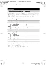
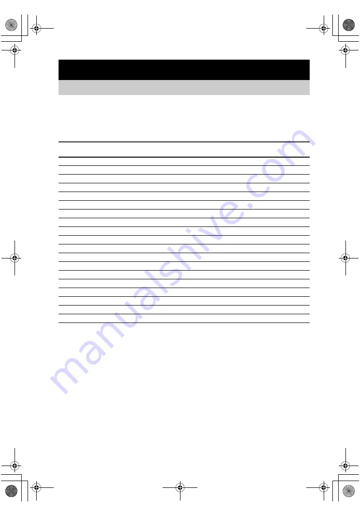
Steps 1a through 1c beginning on page 6 describe how to hook up your components to this receiver. 
Before you begin, refer to “Connectable components” below for the pages which describe how to 
connect each component.
After hooking up all your components, proceed to “2: Connecting the antennas” (page 13).

Connectable components

a)

Model with a DIGITAL OPTICAL OUTPUT or DIGITAL COAXIAL OUTPUT jack, etc.

b)

Model with a MULTI CH OUTPUT jacks, etc. This connection is used to output the audio decoded by the 
component’s internal multi channel decoder through this receiver.

c)

Model equipped only with AUDIO OUT L/R jacks, etc.

d)

Model with component video (Y, P

B

/C

B

/B-Y, P

R

/C

R

/R-Y) input jacks.

Getting Started

1: Check how to hookup your components

Component to be connected

Page

DVD player

With digital audio output

a)

6–7

With multi channel audio output

b)

9–10

With analog audio output only

c)

6–7

TV monitor

With component video input

d)

7 or 10

With composite video input only

12

Satellite tuner

With digital audio output

a)

6–7

With analog audio output only

c)

6–7

Super Audio CD/CD player

With digital audio output

a)

8

With multi channel audio output

b)

9

With analog audio output only

c)

11

MD/Tape deck

With analog audio output only

c)

11

Multi channel decoder

9

VCR, camcorder, video game, etc.

12

GB01COV_HT-DDW970-AU.book  Page 4  Wednesday, June 8, 2005  7:08 PM

Summary of Contents for HT-DDW1000

Page 1: ...Janet DATA_DDW970 J9050954_2549734911DDW970AU 2549734911 GB01 COV_HT DDW970 AU fm masterpage Right 2005 Sony Corporation 2 549 734 91 1 Home Theatre System Operating Instructions HT DDW970 GB01COV_HT DDW970 AU book Page 1 Wednesday June 8 2005 7 08 PM ...

Page 2: ...corner of the front panel The instructions in this manual describe the controls on the receiver You can also use the controls on the supplied remote if they have the same or similar names as those on the receiver For details on the use of your remote see pages 41 48 The HT DDW970 consists of Receiver STR K970P Speaker system Front speaker left SS MSP87L Front speaker right SS MSP87R Center speaker...

Page 3: ...in the display 25 Enjoying Surround Sound Using only the front speakers and sub woofer 27 2CH STEREO Enjoying higher fidelity sound 27 AUTO FORMAT DIRECT Selecting a sound field 29 Selecting the surround back decoding mode 31 SURR BACK DECODING Advanced Adjustments and Settings Reassigning the component video input 33 COMPONENT VIDEO INPUT ASSIGN Switching the audio input mode for digital componen...

Page 4: ...y the component s internal multi channel decoder through this receiver c Model equipped only with AUDIO OUT L R jacks etc d Model with component video Y PB CB B Y PR CR R Y input jacks Getting Started 1 Check how to hookup your components Component to be connected Page DVD player With digital audio outputa 6 7 With multi channel audio outputb 9 10 With analog audio output onlyc 6 7 TV monitor With...

Page 5: ...rd supplied Orange F Monaural audio cord Black Tip Audio cord A can be torn into two monaural audio cords F G Component video cord Green Blue Red Notes Turn off the power to all components before making any connections Be sure to make connections firmly to avoid hum and noise When connecting an audio video cord be sure to match the color coded pins to the appropriate jacks on the components yellow...

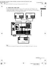
Page 6: ...tput jack to the VIDEO 2 VIDEO IN jack on the receiver 1a Connecting components with digital audio output jacks VIDEO 1 MULTI CH IN FRONT CENTER SUB WOOFER SURROUND VIDEO IN AUDIO IN AUDIO OUT VIDEO IN VIDEO OUT DVD IN VIDEO 2 IN MONITOR OUT VIDEO 2 AUDIO IN COMPONENT VIDEO SA CD CD IN DVD IN Y ASSIGNABLE PB CB B Y PR CR R Y MD TAPE SA CD CD L R L R L R OUT IN IN VIDEO IN DVD AM AUDIO IN AUDIO OUT...

Page 7: ...verted to component video signals or vice versa VIDEO 1 FRONT SURROUND VIDEO IN AUDIO IN AUDIO OUT VIDEO IN VIDEO OUT DVD IN VIDEO 2 IN MONITOR OUT VIDEO 2 AUDIO IN SA CD CD IN DVD IN COAXIAL Y ASSIGNABLE PB CB B Y PR CR R Y MD TAPE SA CD CD L R L R L R OUT IN IN VIDEO IN DVD AM AUDIO IN AUDIO OUT VIDEO OUT L R L R DIGITAL ANTENNA OPTICAL VIDEO 2 IN SUB WOOFER C G COMPONENT OUTPUT VIDEO OUTPUT G C...

Page 8: ...AL IN jack on this receiver Connect the player to the analog input jacks SA CD CD IN jacks Refer to the operating instructions supplied with the Super Audio CD player VIDEO 1 MULTI CH IN FRONT CENTER SUB WOOFER SURROUND VIDEO IN AUDIO IN AUDIO OUT VIDEO IN VIDEO OUT DVD IN VIDEO 2 IN MONITOR OUT VIDEO 2 AUDIO IN COMPONENT VIDEO DVD IN COAXIAL Y ASSIGNABLE PB CB B Y PR CR R Y MD TAPE SA CD CD L R L...

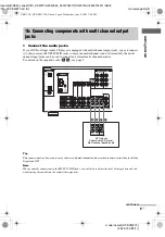
Page 9: ...her than the Dolby Digital and DTS Note When you make connections to the MULTI CH IN jacks you will need to adjust the level of the speakers and sub woofer using the controls on the connected component 1b Connecting components with multi channel output jacks VIDEO 1 FRONT CENTER SURROUND VIDEO IN AUDIO IN AUDIO OUT VIDEO IN VIDEO OUT DVD IN VIDEO 2 IN MONITOR OUT VIDEO 2 AUDIO IN COMPONENT VIDEO S...

Page 10: ...gnals cannot be converted to component video signals or vice versa VIDEO 1 MULTI CH IN FRONT CENTER SUB WOOFER SURROUND VIDEO IN AUDIO IN AUDIO OUT VIDEO IN VIDEO OUT DVD IN VIDEO 2 IN MONITOR OUT VIDEO 2 AUDIO IN SA CD CD IN DVD IN COAXIAL Y PB CB B Y PR CR R Y MD TAPE SA CD CD L R L R L R OUT IN IN VIDEO IN DVD AM AUDIO IN AUDIO OUT VIDEO OUT L R L R DIGITAL ANTENNA OPTICAL VIDEO 2 IN SUB WOOFER...

Page 11: ... FRONT CENTER SUB WOOFER SURROUND VIDEO IN AUDIO IN AUDIO OUT VIDEO IN VIDEO OUT DVD IN VIDEO 2 IN MONITOR OUT VIDEO 2 AUDIO IN COMPONENT VIDEO SA CD CD IN DVD IN COAXIAL Y ASSIGNABLE PB CB B Y PR CR R Y SA CD CD L R L R L R OUT IN IN VIDEO IN DVD AM AUDIO IN AUDIO OUT VIDEO OUT L R L DIGITAL ANTENNA OPTICAL VIDEO 2 IN MONITOR SUB WOOFER A LINE L R OUTPUT LINE L R LINE INPUT OUTPUT A l IN A l OUT ...

Page 12: ...O IN AUDIO OUT VIDEO IN VIDEO OUT DVD IN VIDEO 2 IN MONITOR OUT VIDEO 2 AUDIO IN COMPONENT VIDEO SA CD CD IN DVD IN COAXIAL Y ASSIGNABLE PB CB B Y PR CR R Y MD TAPE SA CD CD L R L R OUT IN IN VIDEO IN DVD AM AUDIO IN AUDIO OUT VIDEO OUT R L R DIGITAL ANTENNA OPTICAL VIDEO 2 IN SUB WOOFER IN VIDEO OUT AUDIO OUT VIDEO IN AUDIO IN OUTPUT INPUT L B VIDEO OUT R AUDIO OUT OUTPUT L B C VIDEO INPUT R L OU...

Page 13: ...r connecting the FM wire antenna keep it as horizontal as possible 2 Connecting the antennas VIDEO 1 MULTI CH IN FRONT CENTER SUB WOOFER SURROUND VIDEO IN AUDIO IN AUDIO OUT VIDEO IN VIDEO OUT DVD IN VIDEO 2 IN MONITOR OUT VIDEO 2 AUDIO IN COMPONENT VIDEO SA CD CD IN DVD IN COAXIAL Y ASSIGNABLE PB CB B Y PR CR R Y MD TAPE SA CD CD L R L R L R OUT IN IN VIDEO IN DVD AM AUDIO IN AUDIO OUT VIDEO OUT ...

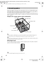
Page 14: ...ker system configuration Tips When you connect 6 1 channel speaker system place the surround back speaker behind the listening position Since the sub woofer does not emit highly directional signals you can place it wherever you want Note Connect the long speaker connecting cords to the surround and surround back speaker terminals and the short speaker connecting cords to the front and center speak...

Page 15: ... the SPEAKERS OFF A B A B button For details see Selecting the speaker system page 39 If you have an additional sub woofer you can connect it to the other SUB WOOFER terminal FRONT A CENTER FRONT B MONITOR OUT NT VIDEO Y PB CB B Y PR CR R Y L R L R L R SPEAKERS SUB WOOFER A A A A B A SPEAKERS FRONT B A SURROUND SURROUND BACK L AUDIO OUT SPEAKERS E e E e E e E e E e E e INPUT R SUB WOOFER Sub woofe...

Page 16: ... Use screws that are suitable for the wall material and strength As a plaster board wall is especially fragile attach the screws securely to a beam and fasten them to the wall Install the speakers on a vertical and flat wall where reinforcement is applied Contact a screw shop or installer regarding the wall material or screws to be used Sony is not responsible for accident or damage caused by impr...

Page 17: ...e buttons on the receiver for the operation 1 Press 1 to turn off the receiver 2 Hold down 1 for 5 seconds PUSH and ENTER appears in the display alternatingly 3 Press ENTER CLEARING appears in the display for a while then CLEARED appears The following are reset to their factory settings All settings in the SPEAKER SET UP LEVEL TONE and CUSTOMIZE menus The sound field memorized for each input and p...

Page 18: ...to the front speaker distance A to a distance 4 5 meters closer to your listening position C If both surround speakers are not placed an equal distance from your listening position set the distance to the closest speaker x DIST X X m Surround back speaker distance Initial setting 3 0 m Lets you set the distance from your listening position to the surround back speaker Surround back speaker distanc...

Page 19: ...ition is designed specifically for implementation of the Cinema Studio EX modes For other sound fields speaker position is not so critical Those sound fields were designed under the premise that the surround speakers would be located behind the listening position but presentation remains fairly consistent even with the surround speakers positioned at a rather wide angle However if the speakers are...

Page 20: ...eiver 2 Press TEST TONE T TONE appears in the display and the test tone is output from each speaker in sequence Front left t Center t Front right t Surround right t Surround back t Surround left t Sub woofer 3 Adjust the speaker levels and balance using the LEVEL menu so that the level of the test tone sounds the same from each speaker For details on the LEVEL menu settings see page 34 Tips The ad...

Page 21: ... muting function will be canceled when you do the following Press MUTING on the remote again Turn the power off Increase the volume To use the headphones Connect the headphones to the PHONES jack When the headphones are connected speaker output is automatically canceled and the SP A and SP B indications in the display turn off When the headphones are connected you can select only the following sou...

Page 22: ...gh the built in tuner Before operation make sure you have connected the FM and AM antennas to the receiver see page 13 Tip The tuning scale is FM 50 kHz AM 9 kHz Automatic tuning If you do not know the frequency of the station you want you can let the receiver scan all available stations in your area 1 Press FM or AM to select the FM or AM band The last received station is tuned in 2 Press TUNING ...

Page 23: ...n you can easily tune in the stations you often listen to Presetting radio stations 1 Press FM or AM to select the FM or AM band The last received station is tuned in 2 Tune in the station that you want to preset using Automatic Tuning page 22 or Direct Tuning page 23 3 Press MEMORY MEMORY appears in the display for a few seconds Do steps 4 to 5 before the display goes out 4 Press PRESET TUNING or...

Page 24: ...ent memory page is tuned in Press SHIFT repeatedly on the remote to change the memory page Changing the information in the display You can check the sound field etc by changing the information in the display Press DISPLAY repeatedly Each time you press DISPLAY the display will change cyclically as follows Index name of the input t Selected input t Sound field currently applied When the tuner is se...

Page 25: ...e decoder is activated Note Dolby Pro Logic IIx decoding does not function for DTS format signals or for signals with a sampling frequency of more than 48 kHz F DTS ES 96 24 DTS lights up when DTS signals are input DTS ES lights up when DTS ES signals are input DTS 96 24 lights up when the receiver is decoding DTS 96 kHz 24 bit signals Note When playing a DTS format disc be sure that you have made...

Page 26: ...around the letters vary to show how the receiver downmixes the source sound L Front Left R Front Right C Center monaural SL Surround Left SR Surround Right S Surround monaural or the surround components obtained by Pro Logic processing SB Surround Back the surround back components obtained by 6 1 channel decoding Example Recording format Front Surround 3 2 Sound Field A F D AUTO L C R SL SR GB01CO...

Page 27: ... woofer Press 2CH 2CH ST appears in the display and the receiver switches to the 2CH STEREO mode The Auto Format Direct A F D mode allows you to select the decoding mode you want for your audio sound Enjoying Surround Sound Using only the front speakers and sub woofer 2CH STEREO Enjoying higher fidelity sound AUTO FORMAT DIRECT A F D mode Display Decoding mode A F D AUTO A F D AUTO As encoded PRO ...

Page 28: ...d type of decoding appears in the display x DOLBY PL PRO LOGIC Performs Dolby Pro Logic decoding The source recorded in 2 channel is decoded into 4 1 channels x PLII MV PRO LOGIC II MOVIE Performs Dolby Pro Logic II Movie mode decoding This setting is ideal for movies encoded in Dolby Surround In addition this mode can reproduce sound in 5 1 channel when watching videos of overdubbed or old movies...

Page 29: ...nt Kim Novak Theater cinema production studio This mode is ideal for watching science fiction or action movies with lots of sound effects x C ST EX C CINEMA STUDIO EX C D CS Reproduces the sound characteristics of the Sony Pictures Entertainment scoring stage This mode is ideal for watching musicals or films where orchestra music is featured in the soundtrack About CINEMA STUDIO EX modes CINEMA ST...

Page 30: ...ike environment while listening through a pair of headphones Note If you connect a pair of headphones while a sound field is operating the system will automatically switch to HEADPHONE 2CH if using a sound field selected with the 2CH or A F D button or to HEADPHONE THEATER if using a sound field selected with the MOVIE or MUSIC button To turn off the surround effect Press 2CH to select 2CH ST or p...

Page 31: ...n enjoy the surround sound intended by the filmmakers Press SURR BACK DECODING repeatedly to select the surround back decoding mode SB XXXX appears in the display For details see How to select the surround back decoding mode on page 32 Tip You can select the surround back decoding mode using SB XXXX in the CUSTOMIZE menu page 36 Note You can select the surround back decoding mode only when you use...

Page 32: ...1 channel signals d Software encoded with both 5 1 channel signals and an extension stream designed for returning those signals to 6 1 discrete channels Discrete 6 1 channel signals are DVD specific signals not used in movie theaters e This decoder can be used for all 6 1 formats Dolby Digital EX DTS ES Matrix 6 1 DTS ES Discrete 6 1 Note There may be no sound from the surround back speaker in Dol...

Page 33: ...or which this receiver have digital audio input jacks 1 Press input buttons to select the input 2 Press INPUT MODE repeatedly to select the audio input mode The selected audio input mode appears in the display Audio input modes AUTO IN Gives priority to digital signals when there are both digital and analog connections If there are no digital signals analog is selected COAX IN Specifies the digita...

Page 34: ... range of BAL L 1 to 8 BALANCE 0 BAL R 1 to 8 in 17 steps x CTR XXX dB Center speaker level x SUR L XXX dB Surround speaker left level x SUR R XXX dB Surround speaker right level x SB XXX dB Surround back speaker level x S W XXX dB Sub woofer level Initial setting 0 dB You can adjust from 10 dB to 10 dB in 1 dB steps x COMP XXX Dynamic range compressor Lets you compress the dynamic range of the so...

Page 35: ...encoded with multi channel surround effects DVD etc 2 Press MAIN MENU repeatedly to select TONE 3 Press or repeatedly to select the parameter you want to adjust For details see TONE menu parameters below 4 While monitoring the sound press or repeatedly to select the setting you want The setting is entered automatically 5 Repeat steps 3 and 4 to adjust the other items Note You cannot adjust the ton...

Page 36: ...coding mode see page 32 OFF AUTO ON Note You can select the surround back decoding mode only when you use a sound field selected with the A F D button except for the Dolby Pro Logic IIx mode x A V SYNC X Time alignment Y Yes Delay time 68 ms The audio output is delayed so that the time gap between the audio output and visual display is minimized N No Delay time 0 ms The audio output is not delayed...

Page 37: ...sub language will be output through the front right speaker simultaneously M Main Sound of the main language will be output S Sub Sound of the sub language will be output M S Main Sub Mixed sound of both the main and sub languages will be output x COMP V A Component video input assignment Lets you reassign the component video input to another visual input For details see Reassigning the component ...

Page 38: ...an select the character type as follows by pressing or repeatedly Alphabet upper case t Numbers t Symbols To enter a blank space press or repeatedly until a blank space appears in the display If you made a mistake press or repeatedly until the character you want to change flashes then press or repeatedly to select the correct character 6 Press ENTER to store the index name You can set the receiver...

Page 39: ...d all components properly Recording on an audio tape or MiniDisc You can record on a cassette tape or MiniDisc using the receiver See the operating instructions of your cassette deck or MD deck if you need help 1 Select the component to be recorded 2 Prepare the component for playing For example insert a CD into the CD player 3 Insert a blank tape or MD into the recording deck and adjust the recor...

Page 40: ...ing from a video tape or DVD Locate the point where you want to start recording from another audio source select the program source then start playback The audio from that source will be recorded onto the audio track of the video tape instead of the audio from the original medium To resume audio recording from the original medium select the video source again Notes You cannot record a digital audi...

Page 41: ...so may cause a malfunction If you don t use the remote for an extended period of time remove the batteries to avoid possible damage from battery leakage and corrosion The H TV VOL TV CH and MASTER VOL buttons have a tactile dot Use the tactile dot as a reference when operating the receiver and other audio video components Operations Using the Remote RM AAP001 Before you use your remote Remote butt...

Page 42: ...er PSX Satellite tuner Turns the audio and videocomponents on or off Remote Button Operations Function CLEAR 9 CD player DVD player Blu ray disc recorder PSX Satellite tuner Clearsa mistake when you press the incorrect numeric buttons or returns to continuos playback etc DISC ws CD player VCD player Selects a disc directly multi disc changer only DISPLAY qa TV VCR VCD player LD player DVD player R...

Page 43: ...the surround back decoding modes SEARCH MODE ws DVD player Selects searching mode Press to select the unit for search track index etc SHIFT 9 Receiver Selects a memory page for presetting radio stations or tuning to preset stations Remote Button Operations Function SLEEP ef Receiver Activates the sleep function and the duration which the receiver turns off automatically SUBTITLE 8 DVD player Chang...

Page 44: ...nnel entry mode either one or two digit 1 ef Receiver Turns the receiver on or off 8 VCR CD player VCD player LD player DVD player MD deck DAT deck Tape deck Blu ray disc recorder Hard disc recorder PSX Skips tracks Remote Button Operations Function m M 9 CD player VCD player DVD player LD player MD deck Blu ray disc recorder Hard disc recorder PSX Searches tracks in the forward or backward direct...

Page 45: ...buttons Selecting the command mode You can switch the command mode AV1 and AV2 of the remote If the command mode of the receiver and the remote is different you cannot use the remote to operate the receiver To change the command mode of the receiver see page 51 Press AV1 or AV2 while holding down RM SET UP The indicator flashes once twice for AV2 then the command mode switches To check the command...

Page 46: ...e remote automatically exits the programming mode To activate the input after programming Press the programmed button to activate the input you want If programming is unsuccessful check the following If the indicator does not light up in step 1 the batteries are weak Replace both batteries If the indicator flashes 4 times in quick succession while entering the numeric code an error has occurred St...

Page 47: ... MARANTZ 116 ONKYO 112 113 114 PANASONIC 115 PHILIPS 116 PIONEER 117 TECHNICS 115 118 119 YAMAHA 120 121 122 Maker Code s SONY 203 PIONEER 219 Maker Code s SONY 301 DENON 302 JVC 303 KENWOOD 304 Maker Code s SONY 201 202 DENON 204 205 KENWOOD 206 207 208 209 NAKAMICHI 210 PANASONIC 216 PHILIPS 211 212 PIONEER 213 214 TECHNICS 215 216 YAMAHA 217 218 Maker Code s SONY 601 602 603 PIONEER 606 Maker C...

Page 48: ...503 511 512 515 534 544 GRUNDIG 517 534 HITACHI 513 514 515 544 ITT NOKIA 521 522 JVC 516 MAGNAVOX 503 518 544 MITSUBISHI MGA 503 519 544 NEC 503 520 544 PANASONIC 509 524 PHILIPS 515 518 PIONEER 509 525 526 540 RCA PROSCAN 510 527 528 529 544 SAMSUNG 503 515 531 532 533 534 544 SANYO 508 545 546 547 SHARP 535 TELEFUNKEN 523 536 537 538 THOMSON 530 537 539 TOSHIBA 535 540 541 ZENITH 542 543 Maker ...

Page 49: ... the receiver near heat sources or in a place subject to direct sunlight excessive dust or mechanical shock Do not place anything on top of the cabinet that might block the ventilation holes and cause malfunctions Use caution when placing the receiver and speakers on surfaces that have been specially treated with wax oil polish etc as staining or discoloration of the surface may result On operatio...

Page 50: ...of the front speaker which is not outputting any sound There is no sound from analog 2 channel sources Check that the INPUT MODE is not set to COAX IN or OPT IN page 33 Check that you have not selected MULTI CH IN function There is no sound from digital sources from COAXIAL or OPTICAL input jack Check that the INPUT MODE is not set to ANALOG page 33 Check that the INPUT MODE is not set to COAX IN ...

Page 51: ...de Move your audio components away from the TV Remote control The remote does not function The AUX and 12 buttons on the remote are not available for receiver operation Point the remote at the remote sensor on the receiver Remove any obstacles in the path between the remote and the receiver Replace all the batteries in the remote with new ones if they are weak Check if the command modes of the rec...

Page 52: ... W 6 ohms 1 kHz THD 0 7 FRONT2 60 W ch CENTER2 60 W SURR2 60 W ch SURR BACK2 60 W 6 ohms 1 kHz THD 10 FRONT2 100 W ch CENTER2 100 W SURR2 100 W ch SURR BACK2 100 W 1 Measured under the following conditions 240 V AC 50 Hz 2 Depending on the sound field settings and the source there may be no sound output Inputs Analog Inputs Digital Outputs Analog Reproduction frequency range 28 20 000 Hz Tone To c...

Page 53: ...tically shielded Surround surround back speakers Full range Speaker units 80 mm cone type Enclosure type Bass reflex Rated Impedance 6 ohms Dimension w h d Approx Front surround surround back speakers 102 150 126 mm Center speaker 225 102 126 mm Mass Approx Front speaker 0 8 kg Center speaker 1 0 kg Surround surround back speakers 0 7 kg Sub woofer SA WMSP87 Speaker system Active sub woofer magnet...

Page 54: ... 9 22 MUSIC button indicator qd 30 50 PHONES jack ed 21 50 PRESET TUNING wl 23 SA CD CD wd 21 SPEAKERS OFF A B A B 2 15 39 50 SURR BACK DECODING qf 31 TUNING e 22 VIDEO 1 wk 21 VIDEO 2 wj 21 VIDEO 3 wh 21 VIDEO 3 IN PORTABLE AV IN jacks ea 12 2CH button indicator q 27 30 35 1 power 1 17 35 51 ql 18 34 35 38 qk 18 34 36 38 List of button locations and reference pages How to use this page Use this p...

Page 55: ...See Recording E Editing See Recording I Indexing See Naming L Labeling See Naming LEVEL menu 34 N Naming 38 P Preset stations how to 23 how to tune 24 R Recording on a video tape 40 on an audio tape or MD 39 S Selecting component 21 sound field 29 31 speaker system 39 Sleep Timer 38 Sound field customizing 34 pre programmed 29 30 resetting 35 selecting 29 30 SPEAKER SET UP menu 18 Speakers adjusti...

Page 56: ...E SEM_Janet DATA_DDW970 J9050954_2549734911DDW970AU 2549734911 GB10 BKC_HT DDW90 AU fm Sony Corporation Printed in Malaysia model name1 HT DDW970 2 549 734 91 1 GB01COV_HT DDW970 AU book Page 56 Wednesday June 8 2005 7 08 PM ...

Reviews: