


16
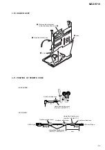
MZ-DH710
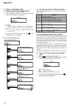
Procedure:
1. Connect the digital multi meter to measuring point (refer to
the following table) and CL433 (GND).
2. Press the
>
key to change the item numberr to 2211.
3. Adjust with
[VOL+]
/
[VOL--]
keys so that the value of digital
multi meter becomes specification value.
4. Press the
X
key to write the adjusted value. (Shifts to the
next item automatically)
5. Repeat adjustment from step 3 until item number 2233.
5. Repeat the next procedures (3-3-2. PwrAdj Adjustments), and
adjust all contents of “table 3-3-1. PwrAdj Specifications”.
3-3-2. PwrAdj adjustments
Repeat the following procedures and adjust all contents of “table 3-
3-1. PwrAdj Specifications”.
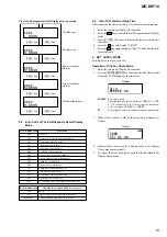
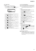
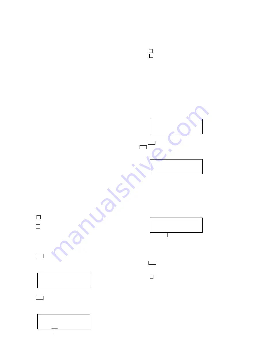
Example Display (Item No. 2211)
adjustment value (hexadecimal)
2 2 1 1
* *
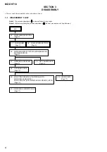
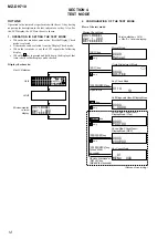
SECTION 5
ELECTRICAL ADJUSTMENTS
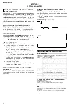
1. PRECAUTIONS FOR ADJUSTMENT
1. Adjustment must be done in the test mode only. After adjusting,
release the test mode. A key having no particular description
in the text, indicates a set key. Also, for the LCD display, the
LCD on the set is shown.
2. Use the following tools and measuring instruments.
•
Digital multi meter
•
Regulated dc power supply (two sets)
•
Thermometer
•
Laser power meter
•
CD adjustment disc TDYS-1 (Part No. : 4-963-646-01)
•
MD1/HiMD1 hybrid adjustment disc MDW-74/GA2
(Part No. : J-2503-022-A)
•
Hi-MD3 adjustment disc HMD1GSDJ
(Part No. : 8-892-388-38) *1
*1) Hi-MD3 adjustment disc (HMD1GSDJ) is consumable.
Therefore if it is used 400 times, exchange it for a new.
2. ADJUSTMENT SEQUENCE
Adjustment must be done with the following order.
Adjustment order:
1. Entering the test mode
Note:
Enter the test mode with a key.
2. Initialize the adjustment value
3. Setting the temperature correction value
4. Power supply voltage adjustment
5. Laser power check
6. Setting the adjustment values
7. Servo Overall adjustment
8. Resume clear
9. Releasing the test mode
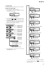
3. ADJUSTMENT OF THE EACH ITEM
3-1. Initialize The Adjustment Value
Procedure:
1. In the test mode (Display Check mode), press the
[VOL--]
key
to enter the Overall adjustment mode.
2. Press the
[DOWNLOAD]
key and display “911 ResOK?”.
3. Press the
X
key to display “911 Reset!” and initialize the
adjustment values.
4. Press the
x
key and back to Display Check mode.
3-2. Setting The Temperature Correction Value
Procedure:
1. Enter the test mode (Display Check mode).
2. Press the
[VOL+]
key to enter the Manual mode.
3. Press the
>
key twice, and press the
[VOL+]
key twice to
display as follows.
Display
5. Measure the ambient temperature.
6. Adjust with
[VOL+]
/
[VOL--]
keys so that the adjusted value
(hexadecimal value) becomes the ambient temperature.
(example: 25
°
C = 19h)
7. Press the
X
to write the adjusted value.
8. Press the
x
key four times and back to the Display Check
mode.
3-3. Power Supply Voltage Adjustment
Adjustment must be done with the following order.
3-3-1. Setting
Procedure:
1. Apply the voltage of 1.2 V to the battery terminals, and enter
the test mode (Display Check mode).
2. Press the
[VOL+]
key to enter the Manual mode.
3. Press the
[VOL+]
key twice to display as follows.
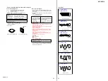
Display
4. Press the
>
key once, press the
[VOL+]
key once, and press
the
>
key once again to display as follows.
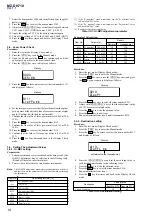
Display
2 2 1 0
P w r A d j
4. Press the
>
key once to select the item number 0131 and
display as follows.
Display
0 1 3 0
T e m p
adjustment value (hexadecimal)
0 1 3 1
# # # S * *
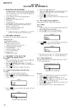
2 0 0 0
P O W E R
Summary of Contents for Hi-MD WALKMAN MZ-DH710
Page 20: ...20 MZ DH710 MEMO ...