background image

86

9-4  Items in the Extended Setup Menu


Ch
apt

er 9  Set

up Men

u

s

310

REC INHIBIT

Select the conditions under which recording is inhibited when F1 (REC INHI) is set 
to “ON” in function menu page P07: E.PRESET.

ALL: 

All tape recording is inhibited. 

CRASH: 

Normal tape recording is inhibited. Select this setting for assemble editing.

VIDEO: 

Recording of video and CTL signals is inhibited.

AUDIO:

 Recording of audio and CTL signals is inhibited.

Note

When F1 (REC INHI) is set to “ON” in function menu page P07: E.PRESET, the 
REC INHI indicator on the lower control panel lights. If an operation inhibited by 
this item is attempted, the REC INHI indicator flashes.

311

ANALOG AUDIO EDIT 
PRESET REPLACE FOR 
CH1

Select how to activate edit preset of each digital audio channel (CH 1 to CH 4, and 
CUE) on this unit using the analog audio preset function of the editor or remote 
controller when using an editor (PVE-500, BVE-600, etc.) or a remote controller 
which cannot control digital audio edit preset. 

The edit preset of each digital audio channel (CH1 to CH4 and CUE) of this unit is 
set to “ON” or “OFF” according to the analog audio preset specified by the editor or 
remote controller.

NODEF

: No definition. 

CH1:

 Follow edit preset of analog channel 1.

CH2:

 Follow edit preset of analog channel 2.

CH1+2:

 Follow edit preset of analog channel 1 or 2. The default settings for each 

item are as follows:

311:

 CH1

312:

 CH2

313:

 NODEF

314:

 NODEF

315: 

NODEF

312

ANALOG AUDIO EDIT 
PRESET REPLACE FOR 
CH2

313

ANALOG AUDIO EDIT 
PRESET REPLACE FOR 
CH3

314

ANALOG AUDIO EDIT 
PRESET REPLACE FOR 
CH4

315

ANALOG AUDIO EDIT 
PRESET REPLACE FOR 
CUE

317

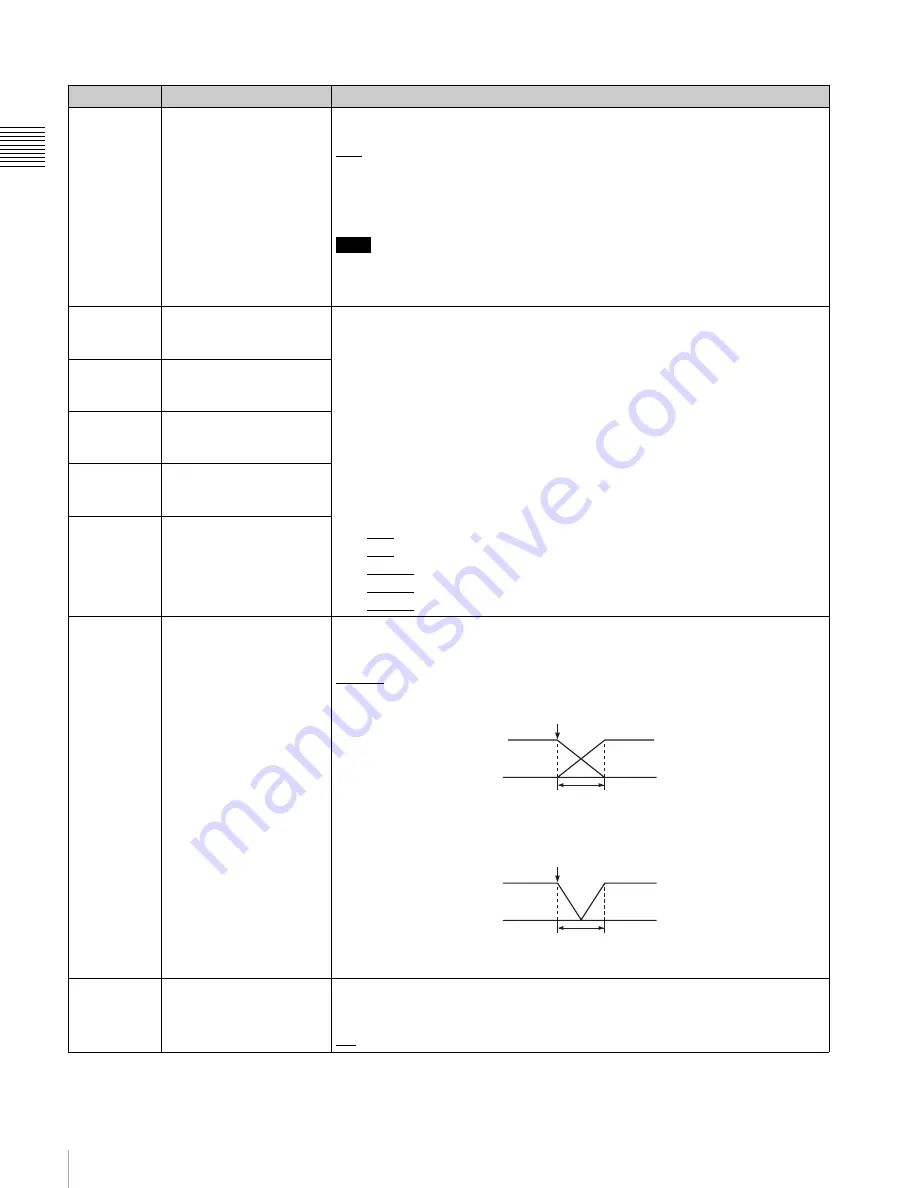
AUDIO EDIT MODE

Select the type of audio transition used for digital audio editing.

CUT: 

Cut editing (audio discontinuity at edit point, and possible noise during 

playback)

CROSS: 

Cross-fade

FI/FO: 

Fade in and fade out

t:

 Time set by menu item 803 “DIGITAL AUDIO FADE TIME”

318

EDIT RETRY

For two-VTR editing, and when this unit is used as the recorder. Select the 
operation if the recorder was not synchronized in time.

OFF: 

Editing is not carried out, and the unit stops.

ON: 

The editing is automatically retried (up to twice).

Menu items in the range 300 to 399, relating to editing operations (Continued)

Item number

Item name

Settings

IN/OUT

t

IN/OUT

t

Summary of Contents for HDW-1800

Page 1: ...HD DIGITAL VIDEOCASSETTE RECORDER HDW 1800 HDW D1800 OPERATION MANUAL English 1st Edition Revised 1 ...

Page 2: ...vironment This equipment generates uses and can radiate radio frequency energy and if not installed and used in accordance with the instruction manual may cause harmful interference to radio communications Operation of this equipment in a residential area is likely to cause harmful interference in which case the user will be required to correct the interference at his own expense You are cautioned...

Page 3: ...d radiation of heat Right Left 4 cm 1 6 inches or more Rear 10 cm 4 inched or more When installing the installation space must be secured in consideration of the ventilation and service operation Do not block the ventilation slots at the left side and right side panels and vents of the funs Leave a space around the unit for ventilation Leave more than 40 cm of space in the rear of the unit to secu...

Page 4: ...ing and Playback 4 1 Recording 33 4 1 1 Preparations for Recording 33 4 1 2 Recording Timecode and User Bit Values 34 4 1 3 Recording Procedure 36 4 2 Playback 37 4 2 1 Preparations for Playback 37 4 2 2 Playback Procedures 37 4 2 3 DMC Dynamic Motion Control Playback 40 Chapter 5 Editing 5 1 Automatic Editing 43 5 1 1 Overview 43 5 1 2 Switch Settings 44 5 1 3 Selecting the Editing Mode 45 5 1 4 ...

Page 5: ...65 8 2 2 Non User Definable Function Menu Pages P100 to P118 69 Chapter 9 Setup Menus 9 1 Setup Menu Configuration 74 9 2 Setup Menu Operations 75 9 3 Items in the Basic Setup Menu 78 9 4 Items in the Extended Setup Menu 81 Chapter 10 Maintenance and Inspection 10 1 Removing a Cassette when Tape Slack Occurs 103 10 2 Head Cleaning 103 10 3 Error Messages 104 10 4 Moisture Condensation 106 10 5 Reg...

Page 6: ...ade when changing formats High precision digital signal processing and range of interfaces Digital signal processing uses HD 4 2 2 component video signals complying with SMPTE 292M which are converted into parallel data and then compressed into HDCAM format The audio signals are based on the AES EBU format and are subjected to digital signal processing without being compressed The unit is equipped...

Page 7: ...ry editing functions are provided to set and amend edit points to preview and review results of editing and so on DMC Dynamic Motion Control editing This allows automatic editing with a varying playback speed memorized beforehand for an edit segment Split editing In insert editing the audio IN and OUT points can be set separately from the video edit points Preread editing This allows you to play b...

Page 8: ... supplied with the board HDV i LINK input option The HKDW 105 i LINK HDV Input Board can be installed in this unit to record i LINK HDV signals from HDV devices onto HDCAM tapes For details on installation settings and operations of the HKDW 105 board refer to the Operation Manual supplied with the board HDV editing is not supported Note ...

Page 9: ...m Configuration The following conceptual diagram shows an example of use BVE series editor Digital cassette Tape control HDSDI Audio video server system HDW 1800 D1800 HDSDI Analog composite HDSDI Video monitor Analog audio Audio monitor Analog composite SDI HD VTR SD VTR ...

Page 10: ...d function buttons to configure the function menu of this unit This manual describes the items related to the function menu as follows based on the standard factory default settings Example Setting F6 PB EE in function menu page P01 HOME This indicates that the PB EE function is assigned to function selection button F6 in function menu page P01 which is named HOME ...

Page 11: ... positions between vertical and horizontal ON OFF KEY INHI CONTROL PANEL 12 34 47 12 5 9 9 4 S D I 2 F A S M LTC C O N F I 1 0 8 0 1 0 8 0 D F LTC EXT LTC R RUN PROLL HOME VIDEO IN SDI EDIT E PRESET CLR CNT HOME PB EE PB CONFI ENABLE COUNTER CTL MENU TCG SET L R 1 SDI1 3 4 BANK3 R E M 2 0 m i n H D C O N D VITC L R 2 ANA2 2 60 40 30 20 10 0 dB L R 3 SDI3 1 L R 4 AES4 4 60 40 30 20 10 0 dB L R CUE ...

Page 12: ... 50P connector The button lights when pressed RS 232C indicator This indicator lights when this unit is communicating with a device connected to the RS 232C connector c EJECT button To eject the cassette press this button While the cassette is being ejected this button lights Ejecting with the EJECT button is a local operation It is not possible to eject a cassette in another VTR by remote control...

Page 13: ...UN 1Menu control section see page 13 4 MULTI CONTROL knob and PUSH SHIFT indicator see page 20 7 Search control section see page 21 6 REC INHI indicator see page 21 5 Tape transport control section see page 20 2 Audio level control knobs see page 19 3 ALARM indicator and KEY INHI indicator see page 20 12 34 47 12 5 9 9 4 S D I 2 F A S M LTC 1 0 8 0 1 0 8 0 D F LTC EXT LTC R RUN PROLL HOME VIDEO IN...

Page 14: ...s the items shown in the function display mode 1 System information System frequency During operation the system frequency is indicated as 59 94 50 29 97PsF 25PsF 24PsF or 23 98PsF Output line information Output line information is indicated as shown below VIN 1080 The unit is in E E mode 1080 The unit is in PB mode 60Hz 1080 An HDCAM tape containing material recorded at different frequencies is c...

Page 15: ...64 Name of function menu page This displays the name of the current function menu page Function button display area A total of 10 function buttons are displayed for each function menu page five each on the left and right sides of the LCD Function button name This is the name of the function button Function button settings This is the setting of the function button 3 Audio level meter block 1 Digit...

Page 16: ...pes of digital track audio level indication As shown below the indications are different for each type FULL PEAK0 The maximum level is indicated as 0 dB FULL REF 0 The reference level is indicated as 0 dB FINE The region near the reference level 3 to 2 75 dB is enlarged for display For details on FINE and FULL see the settings of F4 MT SCALE in function menu page P08 AUD INP For details on REF 0 a...

Page 17: ...0 level indication Example of FINE level indication 5 Time data information Time data display This displays values such as timecode values user bit values and CTL counts Error messages are displayed as up to 10 alphanumeric characters Tape load mark This appears when a cassette tape is currently loaded The abbreviations show information about the tape format a Cleaning mode is activated automatica...

Page 18: ...evices connected to the unit by 9 pin connectors are being operated simultaneously from the control panel R CTRL This unit is being operated from the control panel as a recorder when two units are being used for editing P CTRL A device connected to this unit by a 9 pin connector is being operated from the control panel as a player when two units are being used for editing TCG mode This indicates t...

Page 19: ...e The VIDEO page allows you to make settings for items relating to video P4 AUD INP button This button selects the AUD INP audio input function menu page The AUDIO page allows you to make settings for items relating to audio P5 PAGE DOWN button Each time this button is pressed the function menu page changes in the order P01 t P02 t P03 t P04 t P05 t P06 t P07 t P08 t P01 When this button is presse...

Page 20: ...is lit when you press this knob in In this state the value of the setting changes by a greater amount when you turn the knob 5 Tape transport control section a REC record button To start recording press this button together with the PLAY button turning it on To monitor in E E mode When the unit is in stop mode pressing the REC button lights the button and allows you to monitor the video and audio ...

Page 21: ... on For details of playback in shuttle mode see the description of the search dial 4 b JOG button To use the search dial for playback in jog mode press this button turning it on For details of playback in jog mode see the description of the search dial 4 c VAR variable button To use the search dial for playback in variable speed mode press this button turning it on For details of playback in varia...

Page 22: ... the search dial so that the SHUTTLE button lights then rotate the search dial Playback is carried out at a speed determined by the angular position of the search dial Playback speed ranges are as follows HDCAM tape 50 times normal speed 59 94i 29 97PsF mode 58 times normal speed 50i 25PsF mode 60 times normal speed 24PsF 23 98PsF mode Digital Betacam tape 50 times normal speed MPEG IMX tape 78 ti...

Page 23: ...e 23 2 Analog video input output section see page 24 3 Digital audio input output section see page 24 4 Digital signal input output section see page 24 5 Power supply section see page 25 6 External device connectors see page 25 7 Timecode input output section see page 26 8 Audio monitor signal output section see page 26 Air inlet Air outlet HDV IN connector OPTION see page 26 AUDIO INPUT LOW OFF H...

Page 24: ... When the setting of F5 CHARA in function menu page P04 MISC 1 is ON connector 3 SUPER outputs a signal with superimposed timecode menu settings alarm messages and other text information 3 Digital audio input output section a AUDIO INPUT AES EBU connectors BNC type Input two sets 4 channels CH1 2 and CH3 4 of AES EBU format digital audio signals b AUDIO OUTPUT AES EBU connectors BNC type Output a ...

Page 25: ...l connector D sub 9 pin For remote control of the internal digital video processor connect the optional HKDV 900 Video Remote Controller Always power off this unit before connecting the video remote controller c REMOTE 1 IN 9P remote control signal input connector D sub 9 pin When using this unit together with another HDCAM VTR and a BVE series BVE 700 900 910 2000 9000 9000P 9100 9100P or other e...

Page 26: ...tor of the other device first 7 Timecode input output section a TIME CODE IN connector XLR 3 pin female To record timecode from an external device input a timecode signal from the timecode output connector of the external device b TIME CODE OUT connector XLR 3 pin male This outputs a timecode according to the operating state of the unit as follows During playback the playback timecode By setting s...

Page 27: ...M2100 The following figure shows example connections to use this unit HDW 1800 D1800 as recorder and the HDW A2100 M2000 unit as player 1 The optional BKM 62HS HDSDI SDI Input Adaptor is required REMOTE 1 IN 9P SDI OUTPUT 3 SUPER HDSDI OUTPUT3 SUPER HDSDI INPUT REF VIDEO INPUT HDSDI OUTPUT REF VIDEO INPUT REF VIDEO INPUT Reference signal 75Ω termination switch OFF 75Ω termination switch ON HDW 180...

Page 28: ...th the REF signal When there is no REF signal input whereas REF is selected no external reference signal is used In this case the unit synchronizes with the internally generated reference signal 3 2 2 Connecting Reference Signals Connect reference signals as shown below according to the way in which the unit is to be used Connections for recording from a switcher or signal generator P03 VID PROC F...

Page 29: ...tadata Items relating to video control Items relating to audio control Items relating to digital processing For more information about the items of these menus and how to use them see Chapter 9 Setup Menus page 74 For detailed information about items and setting operations relating to the digital hours meter in the basic setup menu see Section 10 5 1 Digital Hours Meter page 106 This unit saves me...

Page 30: ... mark blank Fields 1 and 3 for 59 94i 29 97PsF mode or fields 1 3 5 and 7 for 50i 25PsF mode Fields 2 and 4 for 59 94i 29 97PsF mode or fields 2 4 6 and 8 for 50i 25PsF mode e VTR control mode Recorder player selection The indication changes as follows according to the VTR control mode the setting of F6 R P SEL in function menu page P06 EDIT P Two unit editing is currently being carried out and th...

Page 31: ...DBY OFF Standby off mode T RELEASE Tape tension release mode STOP Stop mode F FWD Fast forward mode REW Rewind mode PREROLL Preroll mode PLAY Playback mode servo unlocked PLAY LOCK Playback mode servo locked PLAY Variation from normal speed Capstan override mode see page 39 REC Record mode servo unocked REC LOCK Record mode servo locked EDIT Edit mode servo unlocked EDIT LOCK Edit mode servo locke...

Page 32: ...e tape Press in one of the reels with a finger and turn gently in the direction shown by the arrows until there is no slack in the tape To eject a cassette Press the EJECT button Ejecting is a local operation It is not possible to eject a cassette in another VTR by remote control If the tape slacks inside the unit pressing the EJECT button may not eject the cassette For information about how to re...

Page 33: ...B EE PB CONFI ENABLE COUNTER CTL MENU TCG SET L R 1 SDI1 3 4 BANK3 R E M 2 0 m i n H D C O N D VITC L R 2 ANA2 2 60 40 30 20 10 0 dB L R 3 SDI3 1 L R 4 AES4 4 60 40 30 20 10 0 dB L R CUE 3 4 40 20 10 20 10 dB EMPH DATA EMPH DATA CONFI PARARUN Turn on POWER switch see page 12 REMOTE buttons see page 12 off Select the input audio signal see page 69 Select the input video signal see page 65 Select th...

Page 34: ...sing the emphasis deemphasis processing improves the dynamic range by reducing high frequency noise 4 1 2 Recording Timecode and User Bit Values There are two ways of recording timecode as follows Setting an initial value then recording the output of the internal timecode generator Recording the output of the internal timecode generator synchronized with an external timecode generator To set an in...

Page 35: ... with an external signal Use this method to synchronize the timecode generators of multiple VTRs or to record the playback timecode signal from an external VTR without deterioration of the signal waveform In this case the RUN and DF settings are ignored You can synchronize the internal timecode generator with either of the following external timecodes The timecode output LTC of an external timecod...

Page 36: ...e For details see the section To insert a cassette page 32 2 Hold down the REC button and press the PLAY button Recording starts the servo locks and the SERVO indicator lights 3 To stop recording press the STOP button If you record to the end of the tape The tape is automatically rewound to the beginning and stops Setup menu item 125 can be set to disable automatic tape rewind 2 1 3 ...

Page 37: ...the TCG SRC TCG MODE settings see page 66 4 2 2 Playback Procedures This section describes the following playback functions available with this unit Normal playback Playback at normal speed 1 Playback in jog mode Variable speed playback with the speed determined by the speed of rotating the search dial 12 34 47 12 5 9 9 4 S D I 2 F A S M LTC 1 0 8 0 1 0 8 0 D F LTC EXT LTC R RUN PROLL HOME VIDEO I...

Page 38: ...ed range is 1 time normal speed The playback speed range can be 3 times normal speed by changing the setting of setup menu item 116 To carry out playback in jog mode use the following procedure 1 Press the JOG button or search dial so that the JOG button is lit Pressing the search dial toggles between jog mode and shuttle mode 2 Rotate the search dial in the desired direction at the speed correspo...

Page 39: ...rmal speed Digital Betacam 1 to 3 times normal speed MPEG IMX 1 to 3 times normal speed There are detents on the search dial at the still position and at the position for 1 times normal speed To carry out playback in variable speed mode use the following procedure 1 Press the VAR button turning it on 2 Rotate the search dial to the desired angle corresponding to the desired playback speed Playback...

Page 40: ...of character information displayed on the video monitor screen see the descriptions of F5 CHARA in function menu page P04 MISC 1 page 68 and setup menu item 005 page 78 4 2 3 DMC Dynamic Motion Control Playback Overview DMC playback allows you to vary the playback speed for a certain section of a tape in variable speed mode from 1 to 2 times normal speed and store the varying speed in memory for l...

Page 41: ...t F4 DMC begins to flash and playback begins at the speed set in step 4 6 Rotate the search dial to vary the playback speed While the F4 DMC is flashing the speed variations are stored in memory On passing the speed variation end point the F4 DMC changes from flashing to continuously lit pink and the variable speed storing ends 7 Press the STOP button to stop the tape If the F4 DMC is lit before t...

Page 42: ... normal speed Between the speed variation start and end points DMC playback is carried out at the stored speed and then playback continues at normal speed and the tape stops at the on air end point To start playback immediately after preroll Holding down the SHIFT ENTRY button select F2 PREVIEW in function menu page P06 EDIT F2 PREVIEW is lit and after preroll DMC playback is carried out at the st...

Page 43: ...dresses the timecode must be recorded on the tape in correct time sequence i e the sections must be in strictly ascending time order If the timecode values are all in correct time sequence then if there are any discontinuities in the timecode the unit interpolates them using the CTL count To record timecode For automatic editing regardless of the settings of F1 TCG SRC and F2 TCG MODE in function ...

Page 44: ...PH DATA EMPH DATA CONFI PARARUN Z CTL TC TC MENU 59 94 POWER switch I side on see page 12 HDW 1800 D1800 REMOTE buttons see page 12 OFF REC knobs see page 19 Adjust the audio recording levels Edit mode setting section see page 45 Select assemble edit mode or insert edit mode Audio selection function selector buttons see page 69 Select the input audio signal VIDEO IN setting see page 65 Select the ...

Page 45: ...10 OUT in function menu page P06 EDIT When the IN point or OUT point is set the F9 IN or F10 OUT is lit 4 Repeat steps 1 to 3 until all the necessary edit points are set When the edit IN points are set on both the recorder and player F2 PREVIEW and F1 AUTOEDIT flash and preview or editing operation becomes possible To set the edit point automatically Editing requires four edit points each pair of ...

Page 46: ... system automatically calculates and sets the remaining three points Specifically once you have set three of the four video edit points and two of the four audio edit points the remaining three edit points are set automatically regardless of whether these points are for the recorder or player In the figure below the edit points shown within boxes are already set Other edit points recorder audio OU...

Page 47: ... IN and F8 AUD OUT selected While the function items are selected the duration is displayed in the ancillary message display 5 1 5 Modifying and Deleting Edit Points If the edit points are not set correctly for example if an OUT point is before a corresponding IN point and it is not possible to carry out a preview or editing operation In this case modify the erroneous edit point or delete and ente...

Page 48: ... preview Use the following procedure 1 In function menu page P06 EDIT select F6 R P SEL to select the recorder RECDER 2 Holding down the SHIFT ENTRY button select F2 PREVIEW F2 PREVIEW button changes from flashing to continuously lit and the preview is carried out At the end of the preview F2 PREVIEW flashes To stop the preview Press the STOP button The tape stops at the position where you pressed...

Page 49: ...E mode From the OUT point to the postroll point you can monitor the playback image from the recorder The following figure illustrates the descriptions above To monitor with a single monitor for video and audio on both player and recorder You can edit efficiently even if only one monitor is available by using the following procedure 1 Connect the monitor to the recorder 2 In the basic setup menu se...

Page 50: ... point is interruped At the same time F2 PREVIEW and F1 AUTOEDIT start flashing and the unit returns to the state before the editing was started The edit IN and OUT points are preserved so that you can carry out a preview or automatic editing operation again by holding down the SHIFT ENTRY button and selecting F2 or F1 To review the editing results After editing you can check the editing results o...

Page 51: ...rt during DMC editing The following figure illustrates how the tapes run on the player and recorder during DMC editing 5 2 2 Carrying Out DMC Editing To set the edit points and player speed Use the following procedure Tape transport Recorder Preroll Postroll time x final speed IN point OUT point Postroll Playback DMC editing Playback Stop Player Time flow Stop Tape runs at initial speed IN point P...

Page 52: ...pe is prerolled and then the recorder starts operating at normal speed and the player starts at the set initial speed 9 On reaching the IN point and F4 DMC begins to flash rotate the search dial to change the playback speed While F4 DMC is flashing the speed variations are stored in memory On reaching the OUT point the F4 DMC changes from flashing to continuously lit pink and the variable speed st...

Page 53: ...Continuous Editing After an automatic editing the recorder automatically returns to the OUT point For the second and subsequent editing operations you can continue editing by simply specifying the IN and OUT points on the player In this case the current OUT point on the recorder will be the new IN point After automatic editing of one edit segment to carry out continuous editing use the following p...

Page 54: ...ction between video input and output on this unit may cause acoustic feedback howling To prevent this set F2 REF VID see page 67 to REF in function menu page P03 VID PROC and set setup menu item 309 to AUTO1 see page 85 so as to use an external reference signal When the preread mode is selected to prevent feedback due to the loop connection no E E video is output in any editing mode of this unit h...

Page 55: ...e shot marks and so on You can also add a memo mark to a shot mark in the list During tape playback you can add virtual shot marks to the list This is not written on the tape itself and called virtual shot mark To cue up to shot marks By selecting a desired shot mark from the shot mark list you can cue up immediately to that position By button operation you can also cue up to the shot marks adjace...

Page 56: ...nly 10 shot marks will be read from the new tape In the shot mark list see page 57 the data from different cassettes is separated by a separator 6 2 2 Writing Shot Marks To write recording start marks during recording In setup menu item 631 REC START MARK MODE select whether or not to write a recording start mark for each of the three recording modes CRASH REC ASSEMBLE INSERT When you set a partic...

Page 57: ... Operations To display the shot mark list Holding down the SHIFT ENTRY button select F7 LIST in function menu page P104 SHOT MRK All of the shot mark types for which setup menu item 635 LISTING TYPE SELECT is set to ON appear in list form Repeat the same procedure to close the list The function menu display changes as follows Example of list display The following figure shows how the list is organ...

Page 58: ...enu item 635 see Section 9 4 Items in the Extended Setup Menu page 92 With the following procedure you can also specify whether shot marks that have been read are displayed or not 1 With the shot mark list displayed select F5 SETTING You can now select the shot mark types The function menu display changes as follows 2 Select F1 PREV or F2 NEXT to select a shot mark type 3 Select F4 ON or F3 OFF to...

Page 59: ...ERASE lights in pink 5 When the shot mark has been erased close the shot mark list The F2 REC ERS setting returns to OFF when shot mark erasure is complete 6 2 4 Cuing Up to Shot Marks To cue up to a selected shot mark Use the following procedure 1 Turn the MULTI CONTROL knob to select the desired shot mark from the shot mark list 2 Select F9 PREROLL To cue up to shot marks adjacent to the current...

Page 60: ...ct whether to record a Basic UMID or an Extended UMID by using setup menu item 655 UMID RECORDING For more information about setup menu item 655 see page 93 To select whether to inherit or generate the UMID When recording a UMID you can select whether to inherit copy the UMID contained in input signals or generate a new UMID Make this selection by using setup menu item 656 MATERIAL NO For more inf...

Page 61: ... do not change the other items select F10 EXIT If you change the other items COUNTRY and ORGANIZATION select F5 ITEM and repeat as in steps 2 to 7 If you changed other setup menu items before setting the Stored Ownership the changes are confirmed by step 7 To cancel changes and exit the setup menu Select F10 EXIT before finishing step 6 To set the time zone The UMID uses the UTC Coordinated Univer...

Page 62: ...menu display section of the control panel and on the video monitor To display the UMID In function menu page P05 MISC 2 select F2 UMID For more information about function menu operations see Section 8 1 2 Function Menu Operations page 64 The UMID appears in the menu display of the control panel and on the video monitor For examples of the UMID displayed on the video monitor see the next section UM...

Page 63: ...itude data indicating the distance from sea level is displayed in this format The meaning of the characters and strings shown is as follows S 1st character Indicates position data from a Sensor R is shown for position data from the recording device Recorder and T is shown for Target position data 2nd character Indicates higher than sea level indicates lower than sea level XXXXXXXm Altitude data un...

Page 64: ...erations To display the function menu If the LCD is in video display mode without the function menu displayed press the DISPLAY button to switch the LCD mode to function display mode or function video display mode Function menu operations are not possible in video display mode To select function menu settings with the function buttons You can select the next setting under each button name by press...

Page 65: ...tion button display area When you press the F9 or F10 button the function menu page changes to allow you to set the menu items for F9 or F10 respectively For more information about changing user defining the functions of function buttons and menu page selection buttons and the settings of user definable function menu pages refer to the Maintenance Manual Volume 1 8 2 Function Menu Item List The fu...

Page 66: ... the timecode with which the internal timecode generator synchronizes INTERNAL Synchronizes according to the initial preset value set by control panel operation or by control from the device connected to the REMOTE1 IN 9P connector or synchronize with the timecode of the playback tape EXT LTC Synchronizes with the external timecode signal input to the TIME CODE IN connector VID IN Synchronizes wit...

Page 67: ...ase fine adjustment With the displayed setting flashing turn the MULTI CONTROL knob to adjust the output signal sync phase across the range 200 ns relative to this unit s input reference signal The value indication ranges from 0 to 1028 Adjust this item when you want to adjust the output signal sync phase precisely to match a reference signal or to make further fine adjustment when connecting this...

Page 68: ...r framing may not be continuous at edit points 8F The capstan servo locks in units of 8 fields For tape output color framing matches the reference signal selected with F2 REF VID in P03 VID PROC In assemble editing color framing is continuous at edit points The setting is fixedly 2F when the system frequency is 23 98PsF or 24PsF Item Setting F2 No function assigned F3 PREREAD Specify whether to pr...

Page 69: ...emble edit preset setting F6 INS VID Edit preset setting for video track F7 INS A1 Edit preset setting for A1 track F8 INS A2 Edit preset setting for A2 track F9 INS A3 Edit preset setting for A3 track F10 INS A4 Edit preset setting for A4 track Item Setting F1 EMPHASIS Specifiy whether to add audio emphasis to analog audio input signals ON Add audio emphasis OFF Do not add audio emphasis F2 AUD M...

Page 70: ...rack 1 to 4 using this item REC TRAC and specify the audio input channel from which signals are recorded to the specified audio track using F1 INP A1 to F4 INP A4 When the F1 to F4 buttons are pressed simultaneously a maximum of two input channels can be mixed and recorded to a single audio track When F5 CLR MIX is selected all track settings are restored to the factory default values F10 RETURN R...

Page 71: ...nge sub item selection page F7 No function assigned F8 No function assigned F9 SET Confirm setup menu setting changes and return to the previous page F10 EXIT Cancel setup menu setting changes and return to the previous page Item Setting F1 No function assigned F2 No function assigned F3 No function assigned F4 No function assigned F5 RETURN Jump to P108 SETUP TOP F6 SELECT Jump to the sub item se...

Page 72: ...us page Item Setting F1 PREV Select the previous item left up F2 NEXT Select the next item right down F3 Change the numeric value of a setting item decrement F4 Change the numeric value of a setting item increment F5 No function assigned F6 No function assigned F7 No function assigned F8 No function assigned F9 SET Confirm the numeric value setting changes F10 EXIT Return to the previous page Note...

Page 73: ...tion assigned F5 No function assigned F6 No function assigned F7 No function assigned F8 No function assigned F9 No function assigned F10 EXIT Return to the previous page Item Setting F1 PREV Select the previous TC UB digit F2 NEXT Select the next TC UB digit F3 No function assigned F4 No function assigned F5 ITEM Return to the setup menu item screen F6 No function assigned F7 No function assigned...

Page 74: ... to Items 001 to 019 Settings relating to the preroll time superimposed text information changing system frequency etc Page 78 Items B01 to B20 Settings relating to the menu banks for saving menu settings Page 80 Item group Function Refer to Items 100 to 199 Settings relating to control panels Page 81 Items 200 to 299 Settings relating to the remote control interface Page 83 Items 300 to 399 Setti...

Page 75: ...cribed in the section Displaying a desired menu item see page 75 use the following procedure 1 Select F6 SELECT The current setting value of the selected menu item appears 2 Select F3 or F4 or turn the MULTI CONTROL knob to select the desired setting value To select another menu item and change its setting value Select F5 RETURN to display the menu item list and repeat the procedure for selecting ...

Page 76: ...n To change the settings of menu items without sub items page 75 then set menu item B20 RESET SETUP to bank 4 The message Push SET button appears 2 Select F9 SET The display returns to the menu item list The current menu settings are set to the settings in BANK4 3 Select F9 SET again The settings are saved exiting from the setup menu To switch the system frequency menu item 013 To switch the syste...

Page 77: ...BANK 3 to ON depending on the menu banks you want to save in then select F9 SET To recall settings from a menu bank When recalling the settings saved in one of menu banks 1 to 3 set one of the corresponding menu items B01 RECALL BANK 1 to B03 RECALL BANK 3 to ON then select F9 SET To recall the settings saved in menu bank 4 select bank 4 with menu item B20 PRESET SETUP For details about menu bank ...

Page 78: ...F Do not operate in phase synchronization ON Operate in phase synchronization 005 DISPLAY INFORMATION SELECT Determine the type of text information to be output from the COMPOSITE VIDEO OUTPUT 3 SUPER SDI OUTPUT 3 SUPER and HDSDI OUTPUT 3 SUPER connectors when F5 CHARA is set to ON in function menu page P04 MISC 1 T STA Time data display information and the unit s status T UB Time data display inf...

Page 79: ...fore switching 018 ACTIVE LINE SELECT enabled only when the optional HKDW 104 board is installed and disabled in 24PsF 23 98PsF 24PD and 23 98PD2 mode Determine whether to enable switching of the number of active lines for HDSDI outputs OFF TAPE 720P OFF Disable switching ON Enable switching When ON is selected the menu display changes to enable switching between OFF TAPE and 720P For details on t...

Page 80: ...set Stored Ownership display this item in the menu display and select F9 SET to move to the Stored Ownership setting screen For details see the section To set Stored Ownership page 61 B01 RECALL BANK 1 Set to ON to recall menu settings from menu bank 1 B02 RECALL BANK 2 Set to ON to recall menu settings from menu bank 2 B03 RECALL BANK 3 Set to ON to recall menu settings from menu bank 3 B11 SAVE ...

Page 81: ...ed example in 59 94i or 29 97PsF mode HDCAM cassette Digital Betacam cassette 50 times normal speed MPEG IMX cassette 78 times normal speed Maximum search mode speeds example in 59 94i or 29 97PsF mode HDCAM cassette Digital Betacam cassette 50 times normal speed MPEG IMX cassette 78 times normal speed 104 AUDIO MUTING TIME Select the length of time for audio muting when the unit switches to playb...

Page 82: ...en playing back an HDCAM tape however tape speed characteristic figure TYPE 4 c below applies TYPE3 Tape speed varies linearly over the range 3 to 3 2 during HDCAM tape playback as shown in figure TYPE 3 b below TYPE4 Tape speed varies stepwise as shown in figure TYPE4 c below over the range 2 to 2 Characterized by a zone around 1 and 1 where the tape speed is independent of the search dial rotati...

Page 83: ...ode 125 AUTO REWIND Select whether or not to rewind the tape automatically when recording or playback reaches the end of a tape DIS Not rewind ENA Rewind 130 DISPLAY DIMMER CONTROL Set the brightness of LCD 0 to 7 Set in this range 0 is the brightest and 7 the dimmest 139 LOST LOCK DISPLAY ON CONTROL PANEL Select whether to display the message LOST LOCK on the control panel when the lock is lost O...

Page 84: ...m 713 VIDEO SETUP REFERENCE LEVEL Black Menu item 718 SETUP BLACK LEVEL For details see the description of menu item 718 see page 95 Notes After changing this setting power off this unit or HKDV 900 503 and power it on again This setting is valid only in 59 94i or 29 97PsF mode Menu items in the range 300 to 399 relating to editing operations Item number Item name Settings 301 VAR SPEED RANGE FOR ...

Page 85: ... point is deleted automaically NEG When edit points are set incorrectly such as when an OUT point is before an IN point or an audio OUT point is before an audio IN point the previously set edit point is deleted automaically When too many edit points are specified a warning is given by flashing the name of the edit point button for the unnecessary edit point in the control panel Note Pressing the b...

Page 86: ...nel CH1 to CH4 and CUE of this unit is set to ON or OFF according to the analog audio preset specified by the editor or remote controller NODEF No definition CH1 Follow edit preset of analog channel 1 CH2 Follow edit preset of analog channel 2 CH1 2 Follow edit preset of analog channel 1 or 2 The default settings for each item are as follows 311 CH1 312 CH2 313 NODEF 314 NODEF 315 NODEF 312 ANALOG...

Page 87: ...e TC button 337 EXTERNAL REFERENCE SELECT Select the signal used when this unit is set up by setup menu item 309 and function menu page P03 VID PROC to use an external reference video signal as reference HD Use a high definition reference video signal as reference Input a tri level positive and negative sync signal to a REF VIDEO INPUT connector SD Use a reference video signal Input a video signal...

Page 88: ... protection mode in order to protect the video heads and tape 0 5S to 8M to 30M Set the value in the range 0 5 seconds to 30 minutes 502 TAPE PROTECTION MODE FROM SEARCH Select the protection mode to protect the video heads and tape when in the still playback mode in search mode jog shuttle STEP Step forward at 1 30 times normal speed every 2 seconds STDBY Switch to Standby OFF mode the unit not o...

Page 89: ...ine from 9 to 22 Note You can insert the VITC signal in two lines To insert it in two lines set both menu items 601 and 602 603 ID CODE PRESET Select whether to set the ID code OFF Do not set ON Set To set the ID code Select F9 SET with this menu item displayed in the menu display to enter the ID code setting mode Select F1 PREV or F2 NEXT for digit selection When all required digits have been set...

Page 90: ...GEN CONTROL MODE Select whether timecode is automatically regenerated AS IN In automatic editing in assemble mode or insert mode with this unit as a recorder AUTO EDIT regardless of the settings of F1 TCG SRC and F2 TCG MODE in function menu page P02 TC the timecode generator regenerates according to the timecode on the tape ASSEM In automatic editing AUTO EDIT in assemble mode with this unit as a...

Page 91: ...starting TC for timecode conversion from 25F to 24F OFF Do not set ON Set To set the 25F starting TC Select F9 SET with this menu item displayed in the menu display to enter the starting TC setting mode Select F1 PREV or F2 NEXT for digit selection When all required digits have been set correctly select F9 SET again to save the starting TC and exit the starting TC setting mode 622 24F JUMPING TC S...

Page 92: ...36 MARK SELECT IN REC ASSEMBLE SHOT1 Write shot mark 1 during recording and assemble editing SHOT2 Write shot mark 2 during recording and assemble editing POST Write post marks during recording and assemble editing Menu items in the range 651 to 699 relating to the UMID Item number Item name Settings 651 UMID OUTPUT Select the UMID type to be output off Do not output UMID BASIC Output Basic UMID E...

Page 93: ...ntains a UMID The Basic section does not change during recording An Instance Number indicating that this is the original is generated The Source Pack Date Time when changes with each frame The Source Pack Spatial Co ordinates where are not recorded The Source Pack Stored Ownership who can be set See the section To set Stored Ownership page 61 Menu items in the range 700 to 799 relating to video co...

Page 94: ...bar signal MLTBS Multi burst signal 10STP 10 step signal PLSBR Pulse and bar signal RAMP Ramp signal BLACK Black signal To select the video test signal display function menu page P03 VID PROC hold down the ALT DELETE button then select F1 VIDEO IN To cancel the signal selection select F1 VIDEO IN 713 VIDEO SETUP REFERENCE LEVEL In 59 94i or 29 97PsF mode only Set the video setup level to be added ...

Page 95: ... of the video output signal NAROW Digital blanking narrow WIDE Analog blanking wide When WIDE is selected the horizontal blanking width complies with RS170A and normally the blanking is widened and the image becomes narrower It is recommended to select NAROW at editing then select WIDE for broadcast transmission to output a signal conforming to the standard 727 VIDEO EDIT PREVIEW SWITCHER Set the ...

Page 96: ...oll operations FULL Muted in shuttle mode 803 DIGITAL AUDIO FADE TIME Specify the time for cross fade or fade in out editing of digital audio signals 5ms 10ms 15ms 20ms 25msa 50msb 85ms 115msc Note The cross fade or fade in out operation means that the recording is rewritten from the OUT point for the length specified by this setting Even at the minimum 5ms setting a length of recording correspond...

Page 97: ...al or external reference video signal 823 NON AUDIO FLAG PB HDW D1800 only Controls the non audio flag when the playback format is Digital Betacam Sub item 1 CH1 CH2 During playback except E E mode set the digital audio non audio flag as follows OFF OFF the data is audio ON ON the data is non audio AUTO As follows Tape data has been read and confirmed ON or OFF according to the data Tape data has ...

Page 98: ...not record CH1 2 Record audio channels 1 and 2 CH3 4 Record audio channels 3 and 4 CH1 Record audio channel 1 CH2 Record audio channel 2 Menu items in the range 800 to 899 relating to audio control Continued Item number Item name Settings Menu items in the range 900 to 999 relating to digital processing Item number Item name Settings 901 VIDEO OUTPUT DATA Select the number of quantization bits for...

Page 99: ...OW PROCESS MODE enabled only when the optional HKDW 104 board is installed Select whether to increase the vertical resolution during slow playback by activating the relevant filter OFF Do not increase the vertical resolution during slow playback ON Increase the vertical resolution during slow playback 920 SD SDI H ANC CONTROL Invalid in 24PsF or 23 98PsF mode Select whether to add information to t...

Page 100: ... at which low amplitude signals are not emphasized 0 to FH 938 LEVEL DEPEND THRESHOLD DC Invalid in 24PsF or 23 98PsF mode Adjust the downconverter image enhancer Set the luminance range for edge enhancement 0 to 8 to FH 939 H DETAIL FREQUENCY DC Invalid in 24PsF or 23 98PsF mode Adjust the downconverter image enhancer Set the center frequency for edge enhancement 2 6MHz to 3 4MHz to 3 9MHz to 4 6...

Page 101: ...nverter image enhancer Adjust the maximum detail level added to emphasize the original signal 0 to 20H to 3FH 956 CRISP THRESHOLD UC HDW D1800 only Invalid in 24PsF or 23 98PsF mode Adjust the upconverter image enhancer Set the threshold amplitude at which low amplitude signals are not emphasized 0 to 8 to FH 957 LEVEL DEPEND THRESHOLD UC HDW D1800 only Invalid in 24PsF or 23 98PsF mode Adjust the...

Page 102: ...higher 961 BACKGROUND COLOR UC HDW D1800 only Invalid in 24PsF or 23 98PsF mode Set the color of the part where no material exists background for up converting BACKGROUND COLOR Set the color BLACK Black GRAY Gray BLUE Blue TABLE Set with the following Y PB PR tables Y TABLE Adjust the background Y level 0 to FFH B Y TABLE Adjust the background B Y level 0 to 80 to FFH R Y TABLE Adjust the backgrou...

Page 103: ...ntrusted to a technician who has undergone service training For details refer to the Installation Manual 10 2 Head Cleaning To clean the video heads and audio heads always use the special purpose BCT HD12CL cleaning cassette If you insert the cleaning cassette it is automatically ejected after a head cleaning operation for 10 seconds Follow the instructions with the cleaning cassette carefully as ...

Page 104: ...ed to the COMPOSITE VIDEO OUTPUT 3 SUPER connector HDSDI OUTPUT 3 SUPER connector or SDI OUTPUT 3 SUPER connector Depending on the error code a secondary error message may appear indicating the location of the problem Error message displays To display error messages and codes superimposed on the video monitor it is necessary to set F5 CHARA in function menu page P04 MISC 1 to ON Some error message...

Page 105: ...end have been detected simultaneously 12 TAPE TOP SENSOR Malfunction of tape top sensor has been detected 13 TAPE END SENSOR Malfunction of tape end sensor has been detected 14 FAN MOTOR Malfunction of cooling fan motor has been detected 20 CASS COMP MOTOR Malfunction of cassette compartment up or down operation has been detected 21 REEL SFT MOTOR Malfunction of movement of the reel table correspo...

Page 106: ...nit powered off for about 10 minutes since it takes some time to detect moisture condensation in this state 10 5 Regular Checks 10 5 1 Digital Hours Meter The digital hours meter in the time data display can display seven items of information about the operational history of the unit in each corresponding mode Use it as a guide in scheduling periodic maintenance Display modes of the hours meter H0...

Page 107: ...arrow points to which must be replaced as a whole For information on severe conditions frequent threading unthreading or how to replace components refer to the Maintenance Manual Volume 1 For replacement and checking of components contact a Sony service or marketing representative MULTI CONTROL knob F9 MENU F10 EXIT Component Digital hours meter indication menu item number in parenthesis Guideline...

Page 108: ... a functioning pixel ratio of at least 99 99 Thus a very small proportion of pixels maybe stuck either always off black always on red green or blue or flashing In addition over a long period of use because of the physical characteristics of the liquid crystal display such stuck pixels may appear spontaneously These problems are not a malfunction Note that any such problems have no effect on record...

Page 109: ...0 6 mm s 50i 25PsF 77 4 mm s 24PsF 23 98PsF Digital Betacam 96 7 mm s HDW D1800 only MPEG IMX 64 5 mm s 59 94i 53 8 mm s 50i HDW D1800 only HDCAM record playback time 124 minutes with BCT 124HDL 59 94i 29 97PsF 149 minutes with BCT 124HDL 50i 25PsF 155 minutes with BCT 124HDL 24PsF 23 98PsF Digital Betacam playback time HDW D1800 only 124 minutes with BCT 124L MPEG IMX playback time HDW D1800 only...

Page 110: ...audio CH1 to CH4 signal format Sampling frequency 48 kHz synchronized with video Quantization 20 bits sample Wow and flutter Below measurable level Headroom 20 dB or 18 dB selectable Emphasis T1 50 µs T2 15 µs on off selectable in recording mode Analog input output CH1 and CH2 A D D A quantization 20 bits sample Frequency response 20 Hz to 20 kHz 0 5 dB 1 0 dB 0 dB at 1 kHz Dynamic range 95 dB or ...

Page 111: ... with IEEE 1394 option Output connectors HDSDI OUTPUT BNC 3 including 1 for character superimposition Serial digital 1 485 Gbits s SMPTE 292M COMPOSITE VIDEO OUTPUT BNC 3 including 1 for character superimposition 1 0 Vp p 75 Ω Sync negative SDI OUTPUT BNC 3 including 1 for character superimpositon Serial digital 270 Mbits s SMPTE 259M AUDIO OUTPUT CH1 2 XLR 3 pin male 2 4 dBm at 600 Ω load low imp...

Page 112: ...n the United Kingdom Part No 1 551 631 15 Plug holder 3 613 640 01 Design and specifications are subject to change without notice To prevent electromagnetic interference from portable communications devices The use of portable telephones and other communications devices near this unit can result in misoperations and interference with audio and video signals It is recommended that portable communic...

Page 113: ...up 745 SETUP LEVEL HD a HD Sync Phase 746 SYNC PHASE HD a HD Fine 747 SYNC PHASE FINE HD a D1 Master No corresponding menu item D1 Y No corresponding menu item D1 B Y No corresponding menu item D1 R Y No corresponding menu item D2 VIDEO 715 VIDEO GAIN CONTROL a D2 CHROMA 716 CHROMA GAIN CONTROL a D2 HUE 717 CHROMA PHASE CONTROL HD DC SD UC a SETUP 713 VIDEO SETUP REFERENCE LEVEL OUTPUT LEVEL a c 7...

Page 114: ...o the reference signal 0H or 90H HD advanced 0H Output in sync with the reference signal 90H Output with the phase advanced by 90H HD with respect to the reference signal M3A1 SD PHASE SEL Select the SD video output signal phase with respect to the reference signal 0H or 2H SD advanced 0H Output in sync with the reference signal 2H Output with the phase advanced by 2H SD with respect to the refere...

Page 115: ... 576 50i output is upconverted to 1080 50i d For 480 59 94i output is upconverted to 1080 59 94i e HDW D1800 only Playback tape format System frequency 23 98PsF 24PsF 25PsF 50i 29 97PsF 59 94i HDCAM 23 98PsF No No No 24PsF 25PsF No Yes a No 50i 29 97PsF No No Yes b 59 94i 30PsF No No No 60i Digital Betacam e 50i PAL No Yes c No 59 94i NTSC No Yes d MPEG IMX e 50i PAL Yes c No 59 94i NTSC No Yes d ...

Page 116: ...Stick Duo with your product Note on data read write speed Data read write speed may vary depending on the combination of the Memory Stick and Memory Stick compliant product you use What is MagicGate MagicGate is copyright protection technology that uses encryption technology Before using a Memory Stick When you set the Memory Stick erasure prevention switch to LOCK data cannot be recorded edited o...

Page 117: ...cordance with copyright and other applicable laws The Memory Stick application software may be modified or changed by Sony without prior notice Note that there are certain restrictions on recording stage performances and other entertainment events even if they are recorded for personal use only Memory Stick and MagicGate Memory Stick are trademarks of Sony Corporation Memory Stick Duo and are trad...

Page 118: ...E Edit point cue up and preroll 48 modifying and deleting 47 setting 45 Editing automatic editing 43 continuous editing 53 cross fade editing 7 86 DMC 51 mode selection 45 preread editing 54 quick editing 53 split editing 45 standalone editing 53 EJECT button 12 Error messages 104 Extended setup menu items 81 External device connections 27 connectors 25 F F FWD button 21 F1 to F10 buttons 13 Featu...

Page 119: ...PUT connectors 25 Search control section 21 Search dial 21 Servo lock 21 SERVO indicator 21 Setting a user bit value 35 Setup 29 Setup menu basic menu items 78 configuration 74 extended menu items 81 operations 75 SHIFT ENTRY button 19 Shot mark function list operations 57 operations 56 70 overview 55 reading 56 writing 56 SHUTTLE button 21 Shuttle mode 38 Specifications 109 Split editing 45 Stand...

Page 120: ... for use by the purchasers of the equipment described in this manual Sony Corporation expressly prohibits the duplication of any portion of this manual or the use thereof for any purpose other than the operation or maintenance of the equipment described in this manual without the express written permission of Sony Corporation ...

Page 121: ...Sony Corporation HDW 1800 D1800 SY 3 992 538 02 1 2006 ...

Reviews: