15 (E)
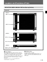
BKS-R3400 Routing Switcher Control Panel
1
Status indicator
This indicates the status of the switcher in the same
manner as that on the front panel of the switcher.
For details, see “Error Indications and Countermeasures”
on page 16(E).
2
CHOP button
When you press this button, it lights in amber.
When you press this button with input and output
selected and change the input selection, the inputs
before and after the change are alternately selected for
approx. 1 second each. This may be convenient for
comparing two signals.
To cancel this function, press the CHOP button again
to make it go dark.
3
Input/output select buttons
These buttons are assigned either for input selection or
output selection from the control terminal.
The buttons assigned for input selection are dimly lit
in green. Those assigned for output selection are
dimly lit in amber.
For matrix settings, first select the output, then select
the input. The selected buttons will light more
brightly.
For details on button settings, refer to the installation
manual for software.
4
LOCK button
When you press this button, it lights in red, disabling
the other buttons. This may prevent misoperation.
To release the lock, press the LOCK button again to
make it go dark.
1
Status indicator
2
CHOP button
4
LOCK button
3
Input/output select buttons
CHOP
LOCK
For future use
Warning
To customers attaching the BKS-R3400
Attaching this panel to the HDS-X3400 disables direct
access to the power switch of the HDS-X3400.
If a fault should occur, turn off the exclusive
disconnect device or disconnect the power cord.


