2-2
VPL-ES7
2-4. ADC
Calibration
2-4-1. RGB Alignment Procedure
1. Power on the projector.
2. Input the following signal from the signal generator to the INPUT A connector.
Timing:
VPL-EX7/EX7IN/EX70:
1024
x
768 : 60 Hz
VPL-ES7:
800
x
600 : 60 Hz
Pattern:
16
gray
pattern
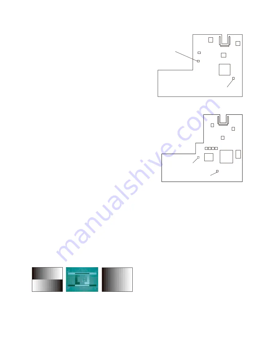
If the pattern shown in Fig. 1 is not available, the pattern shown in Fig. 3 can be used for the adjust-
ment. Use the signal shown in Fig. 2 to run APA. Then, input the signal shown in Fig. 3.
Fig.1
Fig.2
Fig.3
2-3. EEPROM
Replacement
EEPROM of the main board contains the following alignment data
System EEPROM (32 kbits) (U33)
.
V com setting
.
Color temperature
.
RGB gain and offset for PC
.
YUV gain and offset for YPbPr
.
OSD setting
Gamma EEPROM (256 kbits)
(U48: ES7, U20: EX7/EX7IN/EX70)
.
3D gamma
.
Panel gamma
System EEPROM(U33)
ES7 Main Board
Gamma EEPROM
(U48) (Side B)
Gamma EEPROM
(U20)
System EEPROM(U33)
EX7/EX7IN/EX70 Main Board


