1-34 (E)
SRW-5800
1-13. Reference System
For each reference signal of this unit, either of an external reference video signal from the REF. INPUT 1
connector or input video signal from the HD SDI INPUT A connector is automatically selected according
to the setting of setup menu ITEM-005, and the operation mode (PB/EDIT/REC) of this unit. (Refer to the
table 1-13-1 below.)
n
When the setup menu ITEM-005 is set to “external”, be sure to input the external reference video signal
to the REF. INPUT 1 connector.
The record might not be correctly done.
Alarm Display for Video Input Signal and Reference Signal
Blink of the STOP button
The button blinks when the reference signal is not locked to an input video signal.
(This function can be canceled in the setup menu ITEM-102.)
.
When the setup menu ITEM-005 is set to “input”:
The STOP button blinks when the signal is not input to the HD SDI INPUT A connector or when a
different signal from the selected system is input.
.
When the setup menu ITEM-005 is set to “external”:
The STOP button blinks when no reference signal is input to REF. INPUT 1 connector or when the
different reference video signal (REF. INPUT 1) from the system is input.
.
When the setup menu ITEM-005 is set to “auto”:
The STOP button blinks in either of the following cases.
In the REC/EDIT mode, when no signal is input to the HD SDI INPUT A connector or when a different
signal from the selected system is input.
In the PB mode, when no reference signal is input to REF. INPUT 1 connector or when no reference
video signal (REF. INPUT 1) is input.
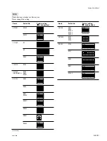
Table 1-13-1. Reference System
ITEM-005 setting
Operation mode
Selected reference signal
REF. INPUT 1
HD SDI INPUT A
PB
EDIT
REC
PB/EDIT/REC
PB/EDIT/REC
external
auto
input

