HCD-SX7/SX7B
5
NOTE OF REPLACING THE COMPLETE NETWORK
BOARD AND CARD WLAN/BT COMBO
When needing to replace the complete NETWORK board or card
WLAN/BT combo, be sure to carry out the following contents.
1. Be sure to replace the complete NETWORK board and card
WLAN/BT combo simultaneously.
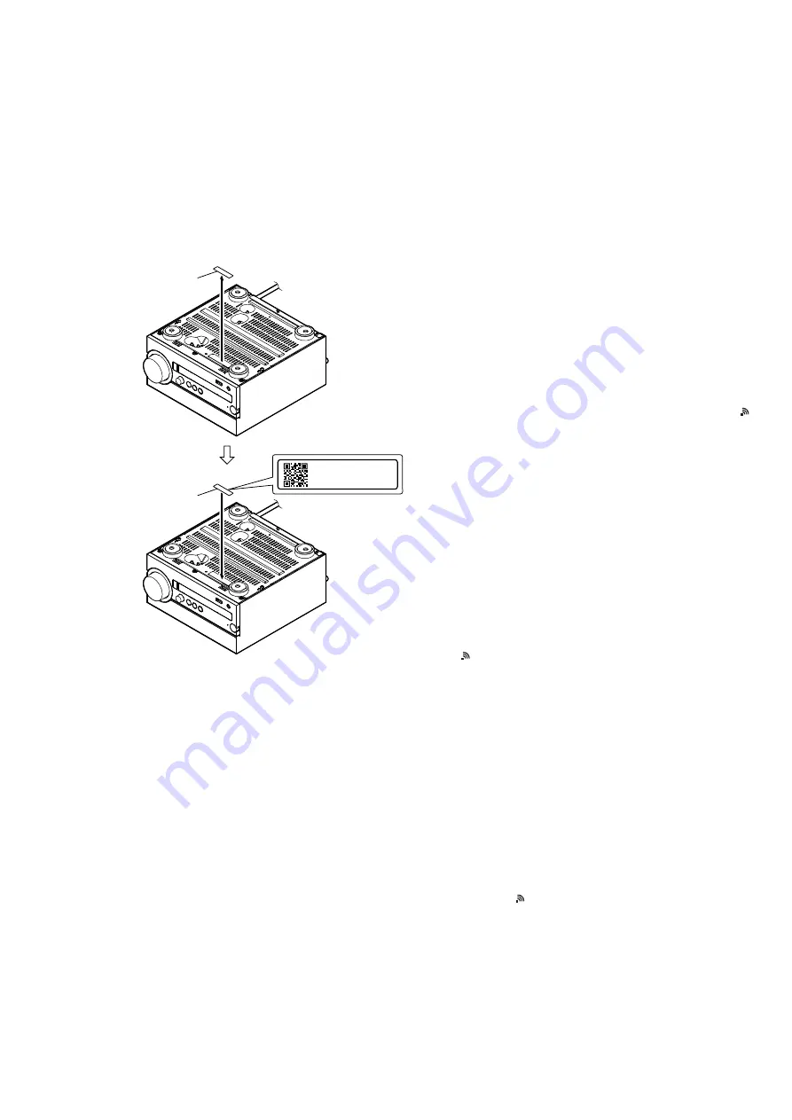
2. When replacing the complete NETWORK board and card
WLAN/BT combo, peel the device ID label stuck on the bot-
tom side of the unit, and stick on the device ID label enclosed
with the new part (Refer to the
fi
gure below).
2
Stick on the new
device ID label
– Bottom view –
1
Peel the device
ID
label.
Device ID: XXXXXXXXXXXX
MAC1 :XX-XX-XX-XX-XX-XX
MAC2 :XX-XX-XX-XX-XX-XX
3. When replacing the complete NETWORK board and card
WLAN/BT combo, refer to “CHECKING OF NETWORK
CONNECTION”.
4. When replacing the complete NETWORK board and card
WLAN/BT combo, the MAC address and DTCP-IP ID have
been changed.
Print the page 7 and page 9, cut it, and hand over it to the cus-
tomer with the unit, when returning the unit that the repair is
completed to the customer.
CHECKING OF NETWORK CONNECTION
When replacing the following parts, be sure to carry out the con-
nection check of network (wired/wireless).
Target parts:
• Complete NETWORK board and card WLAN/BT combo
Note 1:
Be sure to replace the two parts simultaneously.
• Complete MAIN board
• IC206, IC601, IC608, IC609, IC610 and IC705 on the MAIN
board
• Antenna (Ref. No. ANT1) (wireless connection check only)
Note 2:
When replaced the MAIN board or IC206 on the MAIN
board, refer to the “Wi-Fi Startup Guide” of supplied with
this unit and check the operation of AirPlay in iPhone etc.
1. Checking the wireless LAN connection
Necessary Equipment:
• Access point supporting WPS
Procedure:
1. Check that network LAN cable is not connected to the unit.
2. Press the [
@
/
1
] button to turn the power on, and then check “ ”
fl
ashing on the liquid crystal display in about 1 minute.
3. Press the [FUNCTION] button on the remote commander to
select the “NETWORK” function.
4. Press the [MENU] button on the remote commander to the dis-
play the setting menu on the liquid crystal display.
5. Press the [
V
]/[
v
] buttons on the remote commander to select
the “WPS Setting”.
6. Press the [ENTER] button on the remote commander.
(“Ok”
fl
ashes on the liquid crystal display)
7. Press the [ENTER] button on the remote commander.
(“WPS”
fl
ashes on the liquid crystal display)
8. Press the [WPS] button on the access point.
9. When wireless LAN connection is started, “Connecting”
fl
ash-
ing on the liquid crystal display.
10. When wireless LAN connection is completed, “Complete!”
appears for a moment on the liquid crystal display, and then
“ ” lights up on the liquid crystal display.
11. Press the [
@
/
1
] button to turn the power off.
Note:
Refer to “Operating Instructions” or “Wi-Fi Startup Guide” of this
unit’s accessories for details.
2. Checking the wired LAN connection
Necessary Equipment:
• Router
• Network LAN cable
Procedure:
1. Connect the unit to the router with the network LAN cable.
2. Press the [
@
/
1
] button to turn the power on.
3. Press the [FUNCTION] button on the remote commander to
select the “NETWORK” function.
4. Check that “ ” appears on the liquid crystal display.
5. Press the [
@
/
1
] button to turn the power off.
Note:
Refer to “Help Guide” of this unit for details.
SYS SET
2020/02/27 22:53:44 (GMT+09:00)


