


93
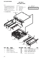
HCD-SC5/SC6/SC8
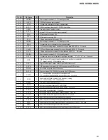
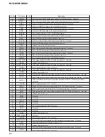
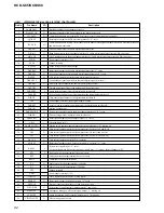
Pin No.
49
50
51
52
53
54
55
56
57
58
59
60
61
62
63
64
65
66
67
68
69
70
71, 72
73
74
75
76
77
78
79
80
81
82 to 84
85, 86
87
88
89
90
91
92
93
94
95
96
97
98
99, 100
I/O
I
O
I
I
O
O
O
O
O
—
—
O
O
—
—
I
O
O
I
O
O
O
—
O
—
—
—
—
I
I
I
I
I
—
I
I
O
I
I
I
I
I
O
O
O
O
—
Pin Name
PROG SW
FM750
TUNED
TUN-DI
TUN-CE
TUN-DO
TUN-CLK
FL-MUTE
FL-CLK
BVDD
BVSS
FL-DATA
FL-CS
LED-CS
LED-CLR
HPSW
DF-RST
PCON3
SW2
F-IN
R-IN
DVD_SEL
NC
RGB_SEL
AVDD
AVSS
AVREF
NC
SW1
SW3
AREA1
SEN2
KEY0 to KEY2
NC
MODEL
RDS-DATA
DVD-POWER
STOP
POWER-SW
SIRCS
WAKE
RDS-CLK
AV-SEL0
AV-SEL1
DF-SW
DF-SYNC
NC
Description
SCAN SELECT switch input terminal “L”: SELECTABLE, “H”: INTERLACE
Power supply for tuner pack on/off control signal output
Tuning detection signal input from the tuner unit “L”: tuned
Serial data input from the tuner unit
Chip enable signal output to the tuner unit
Serial data output to the tuner unit
Serial data transfer clock signal output to the tuner unit
Reset signal output to the fluorescent indicator tube driver “L”: reset
Serial data transfer clock signal output to the fluorescent indicator tube driver
Power supply terminal (+5V) (for bus interface)
Ground terminal (for bus interface)
Serial data output to the fluorescent indicator tube driver
Chip select signal output to the fluorescent indicator tube driver “L” active
Not used
Not used
Connection detection signal input of the headphone jack “L”: no connection, “H”: headphone connected
Reset signal output to the digital audio processor “L”: reset
Standby LED control signal output
Chucking detection switch signal input
Motor drive signal output
Motor drive signal output
DVD select signal output
Not used
RGB select signal output
Power supply terminal (+5V) (analog system)
Ground terminal (analog system)
Reference voltage (+5V) input terminal (analog system)
Not used (fixed at “L”)
Loading out detection switch signal input
Trigger detection switch signal input
Destination setting terminal
Disc loading detection signal input
Key input terminal (A/D input)
Not used (fixed at “L”)
Model setting terminal
RDS serial data input from the RDS decoder
DVD power on/off control signal output “H”: power on
System power stop signal input
AC power detection signal input
Remote control signal input
System wake up signal input by pressing a key on the front panel or remote commander or disc insert detect
switch
RDS serial data transfer clock signal input from the RDS decoder
Audio/video selection signal output
Audio/video selection signal output
selection signal output to the digital audio processor
Sync signal output to the digital audio processor
Not used (fixed at “L”)
Summary of Contents for HCD-SC5
Page 125: ...125 HCD SC5 SC6 SC8 MEMO ...


