background image

HDR-GW55VE/GW77/GW77E/GW77V/GW77VE_L2

2-2

– JAPANESE –

– ENGLISH –

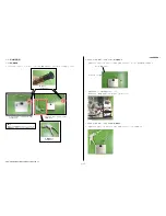
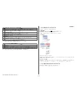
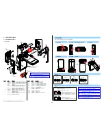
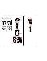
NOTE  FOR  REPAIR

•  Make sure that the flat cable and flexible board are not cracked 

of bent at the terminal.

  Do not insert the cable insufficiently nor crookedly.

•  When remove a connector, don’t pull at wire of connector. It is 

possible that a wire is snapped.

•  When installing a connector, don’t press down at wire of con-

nector. 

  It is possible that a wire is snapped.

•  Do not apply excessive load to the gilded flexible board.

Cut and remove the part of gilt
which comes off at the point.
(Be careful or some
pieces of gilt may be left inside)

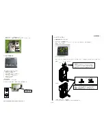
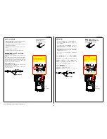
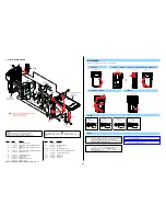
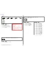
DISCHARGING  OF  THE  CHARGING  
CAPACITOR (C7105)

The charging capacitor is charged up to the maximum 315 V 
potential.
There is a danger of electric shock by this high voltage when the 
capacitor is handled by hand.  The electric shock is caused by the 
charged voltage which is kept without discharging when the main 
power of the unit is simply turned off.  Therefore, the remaining 
voltage must be discharged as described below.

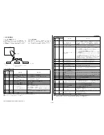
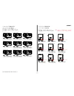
Preparing the Short Jig

To preparing the short jig, a small clip is attached to each end of 
a resistor of 1 k

Ω

 /1 W (1-215-869-11).

Wrap insulating tape fully around the leads of the resistor to 
prevent electrical shock.

1 k

Ω

/1 W

Wrap insulating tape.

1 k

Ω

/1 W

Wrap insulating tape.


R:1 k

Ω

/1 W

(Part code: 1-215-869-11)

Note:

 High-voltage cautions

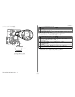
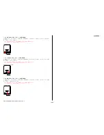
Discharging the Capacitor

Short-circuit between two points with
the short jig about 10 seconds.

(Part code: 1-215-869-11)

C7105

CK-243 Board

CK-243 Board

C7105

修理時の注意

•  フラットケーブルおよびフレキシブル基板の端子面に欠け,

折れ等がないことを確認する。

  また,コネクタへの接続は,差し込み不足や斜め差しになら

ないように注意する。

•  コネクタを取り外す時に,線材部(極細)を持って引っ張ると

断線する恐れがありますので,絶対に線材部(極細)を持って
引っ張らないでください。

•  線材部(極細)を押さえながらコネクタを差し込むと,線材部

(極細)が断線する恐れがありますので,絶対に線材部(極細)

には負担をかけないでください。

•  金メッキされているフレキシブル基板には,強い負担をかけ

ないでください。

వ┵ߩ೸߇ࠇߚࡔ࠶ࠠㇱߪࠞ࠶࠻ߒߡ
㒰෰ߒߡߊߛߐ޿ޕ
㧔ࡔ࠶ࠠ⎕ ߇ࠦࡀࠢ࠲ౝߦᱷߞߡ޿ࠆ
႐ว߽޽ࠆߩߢᵈᗧߒߡߊߛߐ޿㧕

వ┵ߩ೸߇ࠇߚࡔ࠶ࠠㇱߪࠞ࠶࠻ߒߡ
㒰෰ߒߡߊߛߐ޿ޕ
㧔ࡔ࠶ࠠ⎕ ߇ࠦࡀࠢ࠲ౝߦᱷߞߡ޿ࠆ
႐ว߽޽ࠆߩߢᵈᗧߒߡߊߛߐ޿㧕

ストロボ用充電コンデンサ(C7105)の放電

ストロボ用充電コンデンサは最大315Vの電圧で充電され
ています。
この高電圧で充電されたコンデンサに手を触れた場合,
電気ショックを受けます。この高電圧には単にセットの
電源を切っただけでは放電されず,残留しています。こ
のため,下記の方法で残留電圧を放電してください。

ショート治具の準備

ショート治具は1kΩ/1W抵抗  (1-215-869-11)
小型のクリップを接続して作成します。
抵抗器は絶縁テープで完全に覆い電気ショックを受けな
いようにしてください。

1 k

Ω

/1 W

⛘✼࠹࡯ࡊߢᏎߊ

1 k

Ω

/1 W

⛘✼࠹࡯ࡊߢᏎߊ


R:1 k

Ω

/1 W

コンデンサの放電
フラッシュユニットの電源コンデンサ
の端子間をショート治具で約10秒間
接続する。

(Part code: 1-215-869-11)

(Part code: 1-215-869-11)

C7105

CK-243 Board

CK-243 Board

C7105

Summary of Contents for Handycam HDR-GW55VE

Page 1: ...ODIC MAINTENANCE 1 6 PRECAUTION ON REPLACING THE VC 657 BOARD 1 7 ADDITION OF DESTINATION DATA FILE 1 8 PRECAUTION ON REPLACING THE CM 128 BOARD 1 9 PRECAUTION ON REPLACING THE LENS 1 10 SELF DIAGNOSIS FUNCTION 1 11 METHOD OF COPING WITH SHIFT LENS ERROR 1 12 GPS RECEIVING CHECK GW55VE GW77V GW77VE 1 13 PRECAUTION ON REPLACING THE VC 657 BOARD GW55VE GW77V GW77VE 1 14 PRECAUTION ON REPLACING THE C...

Page 2: ...7E GW77VE These specifications are extracted from instruction manual of HDR GW77 GW77V SPECIFICATIONS System Signal format NTSC color EIA standards HDTV 1080 60i 1080 60p specification Movie recording format HD MPEG 4 AVC H 264 AVCHD format Ver 2 0 compatible STD MPEG2 PS Audio recording system Dolby Digital 2ch Dolby Digital Stereo Creator Photo file format DCF Ver 2 0 Compatible Exif Ver 2 3 Com...

Page 3: ...ドット数 総ドット数 921 600ドット 横1 920 縦480 電源部 その他 電源電圧 バッテリー端子入力 3 6 V USB端子入力 5 0 V USB充電 DC 5V 500 mA 600 mA 消費電力 明るさ標準 HD 2 3 W STD 2 1 W 動作温度 0 40 保存温度 20 60 外形寸法 約32 2 mm 約105 5 mm 約70 2 mm 突起部を含む 幅 高さ 奥行き 約32 2 mm 約105 5 mm 約70 2 mm 突起部含む 付属バッテリー装着時 幅 高さ 奥行き 本体質量 約188 g 本体のみ 撮影時総質量 約220 g 付属バッテリー含む 防水 防じん性能 JIS保護等級IP58相当 水深5m 連続60分間 の水中撮影が可能 防水 防じん性能は当社の試験基準によるものです ACアダプター AC UD10 電源 AC 100 V 240 V ...

Page 4: ...orce on the conductor when soldering or unsoldering 1 注意事項をお守りください サービスのとき特に注意を要する個所については キャビ ネット シャーシ 部品などにラベルや捺印で注意事項を 表示しています これらの注意書き及び取扱説明書等の注 意事項を必ずお守り下さい 2 指定部品のご使用を セットの部品は難燃性や耐電圧など安全上の特性を持った ものとなっています 従って交換部品は 使用されていた ものと同じ特性の部品を使用して下さい 特に回路図 部 品表に0印で指定されている安全上重要な部品は必ず指定 のものをご使用下さい 3 部品の取付けや配線の引きまわしはもとどおりに 安全上 チューブやテープなどの絶縁材料を使用したり プリント基板から浮かして取付けた部品があります また 内部配線は引きまわしやクランパによって発熱部品や高圧 部品に...

Page 5: ...e activated by water splashes on the screen icons The touch panel cannot be operated underwater Use the buttons of the camcorder to perform shooting operations Do not subject the camcorder to shock such as from jumping into water Do not open and close the battery memory card jack cover while under near water This camcorder sinks in water Place your hand through the hand strap to prevent the camcor...

Page 6: ...r flow is an example and is not compulsory Modify this flow as needed according to the repair standard and other necessary documents for each area To maintain the waterproof performance of this unit annual replacement charged of the waterproof packing is recom mended in the user s manual and other documents START Within one year from purchase No Was a problem on immersion indicated No Yes No OK Is...

Page 7: ...cking deformed Is any scratch or crack present on exterior parts Is there any trance of immersion No OK Yes See page 1 2 Yes Clean the waterproof packing Unrepairable Remove foreign object from the water stopping area replace exterior parts waterproof parts etc When the unit cannot be repaired take individual measures Conforming to warranty provisions area judgment Note 2 Judge whether the unit is...

Page 8: ... the left side connector 2 Remove the side mounted screw set the two dry cell batteries type 9V DC power supply can be use in place of the dry cell batteries DC12 V to 24 V 1 3 4 Operation of Pressure Indicator Perform the setting Focus mode 40 0 kPa 1 Press the MODE button for 3 seconds or more 2 Press the MODE button at 1 time 3 Press the button and select the Foc mode 4 Press the MODE button at...

Page 9: ... 5 0 kPa 5 Wait 30 seconds with setting air switch to close and write the indicated value 6 In addition leave for 1 minute and check the pressure changes value is satisfied the following value by comparing between the written indicated value and indicated value Body side Specification value 0 32 kPa or less OK 0 33 kPa or more NG Caution Do not open the connector cover and the battery memory card ...

Page 10: ...emoving the vacuum pad ENGLISH 4 The change value is getting settle wait 120 seconds with keeping the pressure at around the 5 0kPa within 0 0kPa to 10 0kPa Caution Do not operate the hand pump after settling the change value If operate the hand pump again wait 120 seconds form then 5 Write the indicated value leave for 1 minute and check the pressure changes value is satisfied the following value...

Page 11: ...hen replacing the board Note When replacing the board it is necessary to change the destination data first To change the destination data execute the DESTINATION DATA WRITE of ADJUST tab in the Adjust Manual DESTINATION DATA When you replace to the repairing board the written destination data of repairing board also might be changed to original setting Start the Adjust Manual in the Adjust Station...

Page 12: ...h by SEUS driver Fig 1 1 7 ADDITION OF DESTINATION DATA FILE If the Destination Data file included in the Adjust manual is old DESTINATION DATA WRITE cannot be executed in some cases In that case download a new Destination Data file from the TISS homepage according to the following procedure Note 1 To perform Destination Data Write for this model the Adjust manual of the DSC WX50 series must have ...

Page 13: ...e If the Destination Data file has not been updated contact the Service Headquarters 4 Download the Destination Data file of the relevant model and unzip the file 5 Execute DESTINATION DATA WRITE in the Adjust tab of the Adjust manual Click the START button ENGLISH 6 Click the File Update button in the window 7 A file selection screen opens Select the Destination Data file to be added and click th...

Page 14: ...dicates the repaired by block in which the problem occurred and detailed code of the problem 0 0 3 2 C Repaired by Refer to 1 10 3 Self diagnosis Code Table Indicates the appropriate step to be taken E g 13 32 Turn on power again Block Detailed Code Blinks at 3 2 Hz C Corrected by customer E Corrected by service engineer Format the memory card LCD screen 1 10 3 Self diagnosis Code Table Self diagn...

Page 15: ...ection during handshake function does not work Inspect the image vibration angular velocity sensors SE7701 on the VC 657 board peripheral circuits E 6 2 1 0 Shift lens initializing failure Replacement of lens block Note 3 If an error occurs again replace the VC 657 board E 6 2 1 1 Shift lens overheating Pitch Refer to 1 11 2 E 62 11 Shift Lens Overheating Pitch Occurred E 6 2 1 2 Shift lens overhe...

Page 16: ... periphery Note When the lens block was replaced start the Adjust Manual in the Adjust Station and execute the necessary adjustment items After the adjustment make sure with the STEADYSHOT turned ON that the steadyshot functions appropriately in the handheld operation 1 11 3 E 62 12 Shift Lens Overheating Yaw Occurred Order Order 1 Start the Adjust Manual in the Adjust Station and execute the Meas...

Page 17: ...odel Part No Description A 1885 943 A A 1885 944 A CABINET BOTTOM BLACK CABINET BOTTOM WHITE HDR GW77E JE Model HDR GW55VE AEP UK Model ENGLISH 1 12 GPS RECEIVING CHECK GW55VE GW77V GW77VE After a part of set was replaced or after the set was assembled check the reception of GPS signal How to check the GPS function Bring your camcorder to an open area and set the GPS to ON appears on the LCD scree...

Page 18: ...ON ON REPLACING THE CABINET G 1 15 1 Precaution on ordering the CABINET G The model display adopts the laser printing method Therefore the Cabinet G for replacement differs depending on the destination As similar displays are provided choose the suitable one for order Note After replacing the Cabinet G the serial number for it will be changed to the one exclusive for service use Inform a customer ...

Page 19: ...水中で沈みます 水没防止のためにス トラップをご使用ください 水中でのフラッシュ撮影時 浮遊物に反射して ぼんやりとした白く丸い点が発生することが あります 故障ではありません 水中での撮影時に画像の歪みが気になる場合 は シーンセレクションで 水中 モードに 設定してください レンズに水滴等がついていると きれいに撮影 できないことがあります 水中 水辺で使用した後のお手入 れ 使用後は60分以内で バッテリー 端子 メモ リーカードカバーを開ける前に必ず水洗いし てください 見えないところに水や砂が入り 込んでいることがあり 塩 砂等を付着したま まにしておくと防水性能が劣化します 容器にためた真水に5分程度つけ置いてから 水の中で本体を揺すったり 各ボタンを動かし て ボタンのすきまに入った塩 砂等をしっか りと洗い流してください 洗ったあと 柔らかい布で水滴を拭き取り 風 通しの良...

Page 20: ... での判定 通常修理開始 Note 1 防水関連部品の交換について その必要性を お客様へご説明ください お客様よりの了承を得られた場合は 防水関連部品の交換を行ってください 通常修理終了 通常修理終了 通常修理開始 A Yes NG Yes A 防水関連 部品の確認 Yes 防水部品 の交換 NG 防水関連 部品の確認 防水関連部品 を交換するか お客様へ確認 Note 1 END A セットの状態を確認 セットの形状に変形はないか 止水部に異物が入っていないか 防水パッキンに変形はないか 外装部品に傷やひびは入っていないか 浸水の痕跡はないか No OK Yes Yes 防水パッキン部の清掃 修理不可能 止水部の異物除去 外装関連 防水関連部品の 交換など 修理不能の場合 個別対応 保証規定に準ずる エリア判断 Note 2 修理が可能であるかの判断については 各拠点の修理規定などに ...

Page 21: ...6082 734 1 ࠛࠕ ࠢ ࠬ ࠦࡦࡊ ࠨ ᑼ J 6082 733 A ࠛࠕ ࠢ ࠬ ࡂࡦ ࡐࡦࡊᑼ J 6082 734 A Note ⓨࡄ ߣᚻേ ⓨࡐࡦࡊߪࠛࠕ ࠢࠬ ߩ ୃ ㇱຠߢ ߦ ࠬ ࠢ ࠕࠛޔ ࠇߡ ߔ ޕ 1 3 2 エアリークテスター コンプレッサー式 の組み立て 1 右側のコネクタに真空パット付きのチューブを挿し 左側のコネクタにコンプレッサー 0 40MPa以上 を接続する ࠦࡦࡊ ࠨ ࡘ ࡉ ᄖᒻ 6mm 2 側面のビスを外して 006P乾電池を2本セットする 電池の代わりに DC電源を供給しても使用できます DC12V 24V 1 3 3 エアリークテスター ハンドポンプ式 の組み立て 1 右側のコネクタに真空パット付きのチューブを挿し 左側のコネクタにハンドポンプを接続する ...

Page 22: ...ജዊ Ꮐ ߔ ജᄢ 1 4 エアリークテスト 1 4 1 検査手順 コンプレッサー式 1 エアリークテスターの電源を入れる 2 真空パッドを平らな面に押し当て エアースイッチをOpenにして圧力調整つまみで 5 0付近に調整する 検査圧力 45 0 3 0kPa 3 真空パッドおよびセットの検査孔にゴミの付着がないことを確認し 真空パッドを検査孔の中心に垂直に押し当てて吸着させる OK 傾き NG テスト穴 エアリーク マイクシート カバーテープ マイク 真空パッドは指を添えて垂直に保ち セットに押し当て続けないこと 測定中は チューブに触れないこと 測定値が変化します 振動無い環境下で測定すること 振動が大きい環境下では 真空パッド部より漏れが発生します エアリークテスト時はマイクシート 4 427 606 01 を剥がし カバーテープ マイク 4 427 546 01 を貼り付けてくだ...

Page 23: ... 0 07kPa以内であればOK 40 0kPa 0kPa 30sec 120sec 60sec 測定 45 0kPa 50 0kPa 検査圧力 0 0kPa FFF 5 0kPa 10 0kPa 表示値 1 4 2 検査手順 ハンドポンプ式 1 エアリークテスターの電源を入れる 2 真空パッドおよびセットの検査孔にゴミの付着がないことを確認し 真空パッドを検査孔の中心に垂直に押し当てて保持する OK 傾き NG テスト穴 エアリーク マイクシート カバーテープ マイク 真空パッドは指を添えて垂直に保ち セットに押し当て続けないこと 測定中は チューブに触れないこと 測定値が変化します 振動無い環境下で測定すること 振動が大きい環境下では 真空パッド部より漏れが発生します エアリークテスト時はマイクシート 4 427 606 01 を剥がし カバーテープ マイク 4 427 546 01 ...

Page 24: ...化が 0 07kPa以内であればOK 0 0 10 0の範囲内で 測定を行うこと 40 0kPa 0kPa 120sec 60sec 測定 45 0kPa 50 0kPa 検査圧力 0 0kPa FFF 5 0kPa 10 0kPa 表示値 1 4 3 検査結果NGとなった場合 以下の手順にて確認する 1 BT蓋のパッキンにゴミの付着がないかを確認する 真空パッドにゴミの付着がないかを確認する マイクシート部を傷つけないように マイク穴を塞ぐ 放熱用のシリコンシート 4 174 010 01など をマイク穴に被せる 吸引時間を60秒延長して再度測定を行なう 2 キャビの組立てを確認し 再度測定を行なう 3 上記の確認をしても改善されない場合はキャビL部組 キャビR部組またはパネル部組を交換し 再度測定を行なう 1 5 定期メンテナンス 1 5 1 定期メンテナンス 防水性能を維持するために...

Page 25: ...さい USBシリアルNo セットは 1台毎に異なる固有のID USB Serial No を書き込んだ後 出荷されています 新品の補修用基板には このIDが書き込まれていないので 基板交換後にIDを入力する必要があります Adjust StationからAdjust Manualを起動させて USB SERIAL No INPUT を実行させてください 内蔵メモリー搭載機について 補修用基板に交換後は 最初に下記の手順を実行してください 1 Adjust ManualのADJUSTタブにある DESTINATION DATA WRITE を実行する 2 下記のスクリプトファイルを実行する Fig 1のフローチャートを参照 11DdmMmcReadTestMINI v4 vbe 11DdmMmcMakePartition v4 vbe Note スクリプトファイルはTISSホームページより入...

Page 26: ...just manual の Destination Data ファイルが古い場合 Fig 1 のようなウインドウが表示される OK ボタンをクリックする Fig 1 2 Destination Data Write ウインドウが表示される Adjust manual の保持している Destination Data ファイル のバージョンを確認する Destination Ver ウインドウ 3 TISSホームページにて 新しい Destination Data ファイルを入手したい機種を検索する Destination Data ファイルが更新されている場合 Destination File For 機種名 zip という名称のファイルが登録されてい る 例 Destination File For DSC WX50 zip また Remarks欄にはこの Destination Dat...

Page 27: ...1 8 CM 128基板交換時の注意 角速度センサ 補修用基板と交換する時 角速度センサSE7501 PITCH YAW の感度表示を書き留めてください Adjust StationからAdjust Manualを起動させて GYRO sensor sensitivity adj を実行させてくだ CM 128 BOARD SIDE A PP PITCH 感度表示 YY YAW 感度表示 G2 G1 YY PP SE7501 Note CM 128基板のSE7501 PITCH YAW 感度表示は補修用基板にのみ記載されています 1 9 レンズ交換時の注意 レンズ交換時 補修用レンズ添付のデータシートに掲載のPITCH YAWデータを書き留めてください Adjust StationからAdjust Manualを起動させて GYRO sensor sensitivity Adj を実行させ...

Page 28: ...る アイリス羽根が動作してない場合は レンズドライブブロックのアイリスモー タドライブ VC 657基板CN1001 qf qg ピン を点検する アイリス羽根が動作する場合は アイリス羽根が完全に閉じきることを確認し 以下の内容を確認する アイリス羽根を正常に閉じることができない場合レンズブロックを交換す る アイリス羽根は正常に閉じているが E 61 30が出る場合CMOSブロック組 立との通信ができているかを確認する 正 常 に 画 面 が 出 て い な い 場 合CM 128基 板 のCN7502とVC 657基 板 の CN1004がFP 1524フレキシブル基板で接続されているかを確認する 正常に画面が出ている場合レンズブロックを交換する E 6 2 0 0 手振れ補正が効きにくい PITCH角速 度センサ出力張り付き PITCH角速度センサ CM 128基板SE7501 周...

Page 29: ...な調整項目を実施するこ と 調整後は手ぶれ補正ONの状態にして 手持ち動作で手振れ補正が適切に動作しているこ とを確認する 1 11 2 E E 62 11 シフトレンズオーバーヒート Pitch がでた場合 順序 作業内容 1 Adjust StationからAdjust Manualを起動させて SERVICE タブにある Measure to E 62 11 12 を実施する 2 順序1を実行した後にシフトレンズが動いているか確認する もしシフトレンズが動かない場合はレンズブロックを交換する 注意 動く場合は順序3に進む 3 VC 657基板のIC5501周辺にあるC5526とC5527の出力電圧をオシロスコープで測定する 順序1を実行したときに出力電圧が変化することを確認する 4 出力電圧が変化しないときはレンズブロックを交換する 注意 変化する場合は順序5へ進む 5 電源を切る ...

Page 30: ...する 1 11 4 E 62 20 サーミスタの異常 が出た場合 順序 作業内容 1 電源を入れる 2 レンズブロックとVC 657基板間のフレキシブルフラットケーブルとコネクタの接続を確認する 3 接続に異常がなければレンズブロックを交換する 注意 交換してもエラーが発生する場合はVC 657基板を交換する 注意 レンズブロックを交換した場合は Adjust StationからAdjust Manualを起動させて必要な調整項目を実施するこ と 調整後は手振れ補正ONの状態にして 手持ち動作で手振れ補正が適切に動作しているこ とを確認する 1 12 GPS 受信確認 GW55VE GW77V GW77VE 部品交換やセット組み立て後は GPS 信号受信確認を行います GPS 機能確認方法 空の開けた場所で GPSを ON にすると が表示され 測位準備が行われます 測位できた場合 動画 ...

Page 31: ...885 943 A A 1885 944 A CABINET BOTTOM BLACK CABINET BOTTOM WHITE HDR GW77E JE 仕向 HDR GW55VE AEP UK 仕向 1 15 キャビネット交換時の注意 G 1 15 1 キャビネット G 注文時の注意 機種の表示部はレーザー印字方式を採用しております この為 交換用のキャビネット G は機種 仕向けにより異な ります 類似の表示もありますので 該当するものを選んで注 文してください 注意 キャビネット G 交換後はシリアルナンバーがサービス 専用のシリアルナンバーに変更されます お客様への案 内と修理データのシリアルナンバー変更を行ってくださ い Part No Description A 1885 921 A A 1885 922 A CABINET G BLACK CABINET G WHITE H...

Page 32: ... 1 15 3 US向けモデルのキャビネット G 交換時の注意 交換前のキャビネット G に印字されている 製造年月 下図の 部の表示 と同じ表示のラベルを新しいキャビネット G に貼付け てください 例 下図では 2B のラベルを貼る ラベルはサービス用 キャビネット G に同梱されておらず 個別に供給となります ラベルが必要なときは 4 415 879 01 を注文してください HDR GW77V US CND 仕向 製造年月 ラベルを貼付けてください 1 15 4 韓国向けモデルのキャビネット G 交換時の注意 交換前のキャビネット G に印字されている 製造年月 下図の 部の表示 と同じ表示のラベルを新しいキャビネット G に貼付け てください 例 下図では 2012 04 のラベルを貼る ラベルはサービス用 キャビネット G に同梱されておらず 個別に供給となります ラベルが必要...

Page 33: ...でuHはμHを示します 半導体の名称でuA uPA uPB uPC uPD 等はそれぞれμA μPA μPB μPC μPD を示します The components identified by mark 0 or dotted line with mark 0 are critical for safety Replace only with part number specified Les composants identifiés par une marque 0 sont critiques pour la sécurité Ne les remplacer que par une pièce portant le numéro spécifié Color Indication of Appearance Parts Example SILVER Cabinet s Color...

Page 34: ...g a small clip is attached to each end of a resistor of 1 kΩ 1 W 1 215 869 11 Wrap insulating tape fully around the leads of the resistor to prevent electrical shock 1 kΩ 1 W Wrap insulating tape 1 kΩ 1 W Wrap insulating tape R 1 k Ω 1 W Part code 1 215 869 11 Note High voltage cautions Discharging the Capacitor Short circuit between two points with the short jig about 10 seconds Part code 1 215 8...

Page 35: ...ure DISASSEMBLY Screw 1 4 2 6 4 1 7 8 3 2 6 3 1 Claws 1 Claws 2 Claws 226 181 179 ns 3 Main Board Section See page 2 4 179 179 180 5 5 181 Note 1 Note 2 4 Note 4 Note 3 Note 4 Refer to Assembly 2 Screw tightening sequence when assembling these parts Note 4 Assembly 2 Screw tightening sequence when assembling these parts を参照してください 2 180X 2 Bottom View 180 3 179 X 2 Open the BT Lid 3 Front View 179 ...

Page 36: ...60 55 56 5 52 1 51 61 1 Remove to numerical order 1 to 5 in the left figure DISASSEMBLY Screw 2 180X 2 Right View 180 3 179 X 2 226 X 3 179 X 3 Remove the Tape A 291 3 Right View Back View Left View 179 226 179 4 179 X 4 71 X 2 Right View 71 179 5 71 X 1 Right View 71 Note Note 1 Replace the battery holder BH1001 together when replacing the lithium storage battery BT1001 on the VC 657 board The ba...

Page 37: ...PPING 1 4 Cabinet L Section See page 2 6 102 103 104 106 107 Note 2 Note 3 108 106 109 including CP001 CMOS imager Note 1 110 115 119 116 118 117 172 172 226 172 172 179 111 112 114 113 101 3 2 1 105 1 Remove to numerical order 1 to 3 in the left figure DISASSEMBLY Screw 1 179X 1 Right View 179 Note Note 1 Be sure to read Precautions for Replacement of Imager on page 6 1 of Level3 when changing th...

Page 38: ... 1529 FLEXIBLE BOARD 164 4 427 568 01 CUSHION SPEAKER 165 4 427 579 01 SPRING BT DISCHARGE 166 X 2584 407 1 CABINET L ASSY 167 4 427 598 01 PACKING LR 168 4 427 585 01 HOLDER MICROPHONE 169 4 179 002 21 TAPPING 1 4 BT901 1 780 826 11 TERMINAL BOARD BATTERY C7105 1 118 127 11 CAP ALUMINIUM ELECT 36uF 315V MIC901 1 542 912 11 MICROPHONE UNIT SP901 1 826 837 71 SPEAKER 1 3CM 71 3 208 537 01 0 Z M1 4X...

Page 39: ... WATER SHEET 209 4 427 602 01 ORNAMENT P CABINET C BLACK 209 4 427 602 11 ORNAMENT P CABINET C WHITE 209 4 427 602 21 ORNAMENT P CABINET C BLUE 210 4 427 600 01 COVER O HINGE BLACK 210 4 427 600 11 COVER O HINGE WHITE 210 4 427 600 21 COVER O HINGE BLUE 211 4 427 592 01 COVER V HINGE 212 4 427 607 01 2 MAIN TORASUTA M1 7 RIGHT 213 4 434 441 01 SHEET SW 180 4 179 319 01 TAPPING 1 7 181 4 178 987 41...

Page 40: ...e SPANISH PORTUGUESE GREEK TURKISH 907 4 424 097 41 Operating Guide POLISH CZECH HUNGARIAN SLOVAK 907 4 424 097 51 Operating Guide SWEDISH DANISH FINNISH ROMANIAN 907 4 424 097 61 Operating Guide RUSSIAN UKRAINIAN 907 4 424 097 71 Operating Guide TRADITIONAL CHINESE 907 4 424 097 81 Operating Guide SIMPLIFIED CHINESE 907 4 424 097 91 Operating Guide ARABIC PERSIAN Ref No Part No Description 931 No...

Page 41: ...77 GW77V 991 4 424 092 11 ユーザーガイ ド 英語 991 4 424 092 21 ユーザーガイ ド フランス語 991 4 424 092 31 ユーザーガイ ド スペイン語 991 4 424 092 41 ユーザーガイ ド ポルトガル語 991 4 424 092 51 ユーザーガイ ド 中国語 繁体字 991 4 424 092 61 ユーザーガイ ド 韓国語 Ref No Part No Description GW55VE GW77E GW77VE 991 4 424 093 11 ユーザーガイ ド 英語 991 4 424 093 21 ユーザーガイ ド フランス語 991 4 424 093 31 ユーザーガイ ド ドイツ語 991 4 424 093 41 ユーザーガイ ド イタリア語 991 4 424 093 51 ユーザーガイ ド オランダ...

Page 42: ...ht is blocked side A glow red and side B glow white at certain angles Install the optical filter block with side B facing toward the lens Optical Filter Block Optical Filter Block Glow white at certain angles Glow red at certain angles IR Cut Coated Side A IR Cut Coated Side B 1 6 5 4 3 2 Heat Sink Plate Heat Sink Plate PS Plate PS Plate 1 2 Assembly 2 Screw tightening sequence when assembling the...

Reviews: