background image

43

GTK-XB60

SECTION  5

EXPLODED  VIEWS

Note:

•  -XX and -X mean standardized parts, so 

they may have some difference from the 
original one.

•  Items marked “

*

” are not stocked since 

they are seldom required for routine ser-
vice. Some delay should be anticipated 
when ordering these items.

•  The mechanical parts with no reference 

number in the exploded views are not sup-
plied.

•  Color Indication of Appearance Parts Ex-

ample:

  KNOB, BALANCE (WHITE) . . . (RED)


Parts Color  Cabinet’s Color

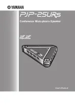
5-1.  SIDE  PANEL  SECTION

1

A

A

speaker cabinet section

BAT1

5

2

3

2

2

2

2

2

2

2

2

2

2

2

2

2

2

2

2

2

4

top panel section

6

6

6

6

6

6

6

6

6

6

7

8

9

10

10

rear side

top side

left side

right side

  1 

9-885-219-47  RUBBER (BLACK 4PCS) (4 pieces, 1 set) 

(for Black)

  1 

9-885-219-48  RUBBER (BLUE 4PCS) (4 pieces, 1 set) (for Blue)

  1 

9-885-219-49  RUBBER (RED 4PCS) (4 pieces, 1 set) 

(for Orange Red)

 2 

9-885-219-01 SCREW 

(M4X20)

  3 

9-885-219-35  SIDE PANEL L (UC2 BLACK) (for L-ch) (Including 

Inside cushion, Inside rubber) (for Black) (US, CND)

  3 

9-885-219-38  SIDE PANEL L (CEL BLACK) (for L-ch) 

(Including Inside cushion, Inside rubber) 

(for Black) (AEP, RU, UK, AUS)

  3 

9-885-219-39  SIDE PANEL L (CEL BLUE) (for L-ch) 

(Including Inside cushion, Inside rubber) (for Blue)

  3 

9-885-219-40  SIDE PANEL L (CEL RED) (for L-ch) (Including 

Inside cushion, Inside rubber) (for Orange Red)

  4 

9-885-219-29  SIDE PANEL R (UC2 BLACK) (for R-ch) 

(Including Inside rubber) (for Black) (US, CND)

  4 

9-885-219-32  SIDE PANEL R (CEL BLACK) (for R-ch) (Including 

Inside rubber) (for Black) (AEP, RU, UK, AUS)

  4 

9-885-219-33  SIDE PANEL R (CEL BLUE) (for R-ch) 

(Including Inside rubber) (for Blue)

  4 

9-885-219-34  SIDE PANEL R (CEL RED) (for R-ch) 

(Including Inside rubber) (for Orange Red)

  5 

9-885-219-41  FOOT PAD (CIRCLE BLACK 4PCS) 

(4 pieces, 1 set) (for Black)

  5 

9-885-219-42  FOOT PAD (CIRCLE BLUE 4PCS) (4 pieces, 1 set) 

(for Blue)

  5 

9-885-219-43  FOOT PAD (CIRCLE RED 4PCS) (4 pieces, 1 set) 

(for Orange Red)

 6 

9-885-219-02 SCREW 

(M3X10)

  7 

9-885-219-91  BATTERY BOX (UC2) (Including Inside cushion) 

(US, CND)

  7 

9-885-219-92  BATTERY BOX (CEL) (Including Inside cushion) 

(Except US, CND)

  8 

9-885-219-93  BATTERY COVER (UC2) (Including Inside cushion) 

(US, CND)

  8 

9-885-219-94  BATTERY COVER (CEL) (Including Inside cushion) 

(Except US, CND)

  9 

9-885-221-60  CUSHION (BATTERY CABLE) (See Note)

  10 

9-885-221-59  CUSHION (BATTERY) (See Note)

  BAT1 

1-853-678-11  LITHIUM ION BATTERY (LIP4160HEPC (SY6))

  Ref. No. 

Part No. 

Description 

Remark

  Ref. No. 

Part No. 

Description 

Remark

•  Refer to “COLOR VARIATIONS” on page 5 

about color variation of the unit.

Note: 

CUSHION (BATTERY CABLE) (Ref. No. 9) and CUSHION 
(BATTERY) (Ref. No. 10) cannot be reused. When replacing 
the LITHIUM ION BATTERY (Ref. No. BAT1), be sure to re-
place them with new parts simultaneously.

Summary of Contents for GTK-XB60

Page 1: ...z rated 15 watts per distortion from 250 milliwatts to 10 kilohms 2 4835 GHz NFC section Maximum output power 60 dBμA m at 10 m Operating frequency 13 56 MHz Lithium ion battery section Usage life of the lithium ion battery When the Speaker Lights are turned off 3 5 hours at the maximum volume level 5 hours at the maximum volume level with the STAMINA mode turned on 14 hours at volume level 17 Whe...

Page 2: ...ervice mark of Apple Inc t Made for iPod and Made for iPhone mean that an electronic accessory has been designed to connect specifically to iPod or iPhone respectively and has been certified by the developer to meet Apple performance standards Apple is not responsible for the operation of this device or its compliance with safety and regulatory standards Please note that the use of this accessory ...

Page 3: ... 10 Schematic Diagram MAIN Board 7 8 30 4 11 Schematic Diagram MAIN Board 8 8 31 4 12 Printed Wiring Board NFC Board 32 4 13 Schematic Diagram NFC Board 32 4 14 Printed Wiring Board BT Board 32 4 15 Schematic Diagram BT Board 33 4 16 Printed Wiring Board KEY Board 34 4 17 Schematic Diagram KEY Board 35 4 18 Printed Wiring Board MIC KNOB Board 36 4 19 Schematic Diagram MIC KNOB Board 36 4 20 Printe...

Page 4: ...es occur such as on IC pins etc Usable with ordinary solder It is best to use only unleaded solder but unleaded solder may also be added to ordinary solder NOTE FOR DISASSEMBLY Lithium ion battery is installed in this unit When disassembling this unit be sure to disassembly after remov ing the connector of lithium ion battery from board lithium ion battery connector XP3 MAIN board front side left ...

Page 5: ...pointed object The system will turn off 2 Press Æ to turn the system back on Notes If the system doesn t turn back on consult your Sony dealer Pairing information is not deleted when you press RESET CHARGING THE BATTERY The system can be used with the built in battery rechargeable instead of connecting the AC power cord to a wall outlet if the battery has been sufficiently charged Connect the AC p...

Page 6: ...D BLOCK Page 11 2 13 BT BOARD Page 13 2 7 MIC KNOB BOARD Page 9 SET 2 8 MAIN BOARD Page 10 2 6 POWER BOARD Page 9 2 10 NFC BOARD Page 12 2 14 BOTTOM PANEL ASSY Page 14 2 15 FRONT PANEL BLOCK 1 Page 15 2 16 FRONT PANEL BLOCK 2 Page 16 2 17 SPEAKER UNIT WF Page 17 2 18 TOP SPEAKER BOARD BOTTOM SPEAKER BOARD TOP LED BOARD BOTTOM LED BOARD Page 18 2 19 SPEAKER UNIT TW Page 19 JIG When disassembling th...

Page 7: ...ar side left side 2 3 LITHIUM ION BATTERY top side front side rear side boss boss 1 four screws M4 u 20 2 battery cover Note 2 When installing the battery cover align the two bosses and two holes 6 lithium ion battery hole hole 3 Remove the lithium ion battery block in the direction of the arrow 10 mm bottom side top side lithium ion battery Right view guide line guide line Rw tR iQVtDOO the thUee...

Page 8: ...0 5 top panel block 1 screw M3 u 10 1 screw M3 u 10 2 4 SIDE PANEL R top side front side rear side 2 two screws M3 u 10 2 screw M3 u 10 6 side panel R 5 Remove the side panel R in the direction of the arrow 1 two foot pads circle 3 two screws M4 u 20 two bosses with two rubbers 4 four claws 1 two foot pads circle 3 three screws M4 u 20 4 four claws 4 five claws two bosses with two rubbers ...

Page 9: ... M3 u 10 4 MIC knob MIC knob rotary encoder rear side 2 two screws M3 u 10 1 MIC KNOB board cable connector XP4 3 MIC KNOB board block 6 party chain button lens 7 MIC KNOB board Note When installing the MIC KNOB board align the two bosses and two holes MIC KNOB board block How to install the MIC knob When installing the MIC knob to the rotary encoder align the directions of the D shaped tip of the...

Page 10: ...7 A A B B 3 FFC TOP LED MAIN XP7 4 POWER board cable connector XP20 rib 2 woofer cable connector XP13 1 tweeter cable connector XP11 7RS YLHZ FFC TOP LED MAIN tweeter cable woofer cable rear side XP20 8 thermal sheet See Fig B 6 four screws 3 u 6 left side right side LJ 3DVWLQJ SRVLWLRQ RI WKH WKHUPDO VKHHW When affixing the thermal sheet affix so that the entire projection of the bottom shell is ...

Page 11: ...ide terminal side 4 four screws M4 u 20 5 board block 2 woofer cable connector XP13 1 tweeter cable connector XP11 3 FFC TOP LED MAIN XP7 LUH VHtting MAIN board XP11 XP13 XP7 7RS YiHZ FFC TOP LED MAIN tweeter cable woofer cable rear side top side ...

Page 12: ...LRQ GLUHFWLRQ IRU WKH 1 ERDUG front side rear side Arrow direction NFC board RWWRP YLHZ 4 Remove the NFC board in the direction of the arrow 1 cushion front side top side top panel block FFC BT MAIN cushion front side 7 0 1 VHWWLQJ rear side 3 Move the FFC BT MAIN to the front side 2 three screws M3 u 10 2 screw M3 u 10 2 screw M3 u 10 RWWRP YLHZ rear side hole boss 4 top handle Note When installi...

Page 13: ...ophone cable XP6 BT board rear side BT board 4 Gradually peel off the BT board with a flathead screwdriver etc Note 3 The BT board is affixed to the top panel with a adhesive sheet When removing the BT board remove slowly so that you do not damage the boss etc of the top panel hole hole two bosses adhesive sheet 6 BT board Note 2 When installing the BT board align the two bosses and two holes 5 Pe...

Page 14: ... not to damage the four bosses bottom side 1 two foot pads flat 1 two foot pads flat 3 screw M3 u 10 3 screw M3 u 10 2 two screws M4 u 20 8 bottom panel assy Note 3 When installing the bottom panel assy remove the used bond and use a new bond to fix the bottom panel assy 7 Remove the bottom panel assy in the direction of the arrow top side front side bond bond bond 6 claw 4 4 bottom side bottom pa...

Page 15: ... a thick screwdriver into the bottom side and widen the gap perform at two places Note 2 Be careful because if a screwdriver is inserted too far in the speaker unit WF may get damaged 3 Insert a thick screwdriver into the top side and widen the gap perform at two places Note 2 Be careful because if a screwdriver is inserted too far in the speaker unit WF may get damaged front side boss front panel...

Page 16: ...ront panel block be careful not to pinch the three cables tweeter cable woofer cable FFC TOP LED MAIN FFC TOP LED MAIN 4 front panel block Note 3 When installing the front panel block remove the used bond and use a new bond to fix the front panel block wood cabinet bottom side front panel block 1 Insert a thick screwdriver into the left side and widen the gap perform at two places Note 2 Be carefu...

Page 17: ...f the speaker terminal to the position shown in the figure below Note 2 When installing the woofer cable make the position of caulking of terminals is outside Note 2 When installing the woofer cable make the position of caulking of terminals is outside left side right side top side wood cabinet terminals position top side terminal wide terminal narrow bottom side woofer cable yellow line terminal ...

Page 18: ...OM LED board Note When installing the BOTTOM LED board align the two bosses and two holes 8 TOP LED board Note When installing the TOP LED board align the two bosses and two holes hole hole 7 FFC TOP LED MAIN XP7 boss boss boss boss bottom side 4 SPEAKER board cable connector XP14 2 two screws M3 u 10 3 Remove the LED SPEAKER board block in the direction of the arrow 3 Remove the LED SPEAKER board...

Page 19: ... u and ADD simultaneously for 5 seconds 4 Each software version are shown by the flashing frequency of LEDs simultaneously Example When the MCU version is v12 the ADD L LED flashes 1 time the ADD R LED flashes 2 times ADD R L Flash 1 time Flash 2 times When the MPEG version is v14 the STAMINA LED flashes 1 time the CHARGE LED flashes 4 times CHARGE STAMINA FUNCTION Flash 1 time Flash 4 times When ...

Page 20: ...Chain FLASH 8M 01U0FLASH 202 crystal 01UCRYSTA 502 USBP USBM XI XO SW NX3DV42GU USB DAC AK4430 DATA4 DATA5 BCLK1 LRCLK1 DATA1 SW 74L VC2 44 BCLK3 LRCLK3 DATA3 XI XO IIC1 From MCU IO 5 For White_LED 5 USB 1 Audio IN 1 L R 2 Party Chain 1 IO 1 For RED_LED Bass IO 1 For Amber _LED Charge IO 2 For Red Green Stanby _LED Charge ROM 256K bytes RAM 32K bytes IIC1 IIC2 DATA0 MPEG Decoder SPHE81 07C Embedde...

Page 21: ... POWER Board White_LED 5 USB 1 Audio IN 1 L R 2 Party Chain 1 Amber_LED Charge Red Green LED Stanby RED_LED Bass For PCM1808 3 YSS952 AS9632 TAS5538 74LVC244 ADC4430 AM4KA340 KXCJK 1013 For RGB LED 4 Flash White LED 4 SN3218 5V_D3 MOS EUP3504 From MCU I O 1 MOS AP2305 I O 1 From MCU 3 3V_D2 Triode BT3906 I O 1 From MCU For PCM1808 3 5V_D1 DC DC TPS54240 STB_12V M O S 23 0 5V Battery 4 pieces 14 4V...

Page 22: ...mber specified Note Les composants identifiés par une marque 0 sont critiques pour la sécurité Ne les remplacer que par une pièce portant le nu méro spécifié Note Among mounted electrical parts on each board only parts that are described in the electrical parts list can be replaced for repairing The parts that are not described in the electrical parts list cannot be replaced with single for repair...

Page 23: ...XB60 GTK XB60 23 23 4 3 PRINTED WIRING BOARD MAIN Board Uses unleaded solder See page 22 for Circuit Boards Location MAIN BOARD COMPONENT SIDE MAIN BOARD CONDUCTOR SIDE A B C D E F G H 1 2 3 4 5 6 7 8 9 10 ...

Page 24: ...R ZD1 ZMM12V 12V ZD1 ZMM12V 12V 100uF 16V CE12 100uF 16V CE12 C389 2 2uF C389 2 2uF ZD4 ZMM5V6 5 6V ZD4 ZMM5V6 5 6V Q18 NPN_3DG3904M Q18 NPN_3DG3904M U21 U21 R6 9 1K 1 R6 9 1K 1 U4 SGM203 2ADJ3 U4 SGM203 2ADJ3 C69 1UF 100V X7R C69 1UF 100V X7R C18 0 1uF 50V X7R C18 0 1uF 50V X7R C9 10uF C9 10uF R58 R58 C25 C25 C36 0 1uF C36 0 1uF R27 47K R27 47K C110 NC 330pF 50V X7R C110 NC 330pF 50V X7R 220uF 25...

Page 25: ..._LRCK GPIO71 HDMI_CEC GPIO72 VDD33 NC NC NC HEAC GPIO132 HEAC SAR_ADI2 HDMI_HPD GPIO136 SAR_ADI1 GPIO135 SAR_ADI0 GPIO134 USB_DM SPI_CE HW_CFG SPI_D0 SPI_CLK HW_CFG SPI_D1 SPDIF_IN1 GPIO33 SPDIF_IN2 GPIO32 BT_EN GPIO31 UART2_RTS GPIO30 AADC_VSS AADC_AVDD MIC_BIAS MIC_IN AIN_L0 AIN_R0 AIN_L1 AIN_R1 EPAD VFD_DAT PWM2 GPIO46 1 2 3 4 CE SO WP VSS SI SCK HOLD VDD Y1 24 576MHz 10PPM Y1 24 576MHz 10PPM C...

Page 26: ...17 3 3K C71 4 7uF 10V X5R C71 4 7uF 10V X5R 220uF 16V CE17 220uF 16V CE17 R270 0 R270 0 R98 51K R98 51K R81 47K R81 47K C72 0 1UF C72 0 1UF R271 0 R271 0 R107 51K R107 51K R140 0 R140 0 P3 7PIN CKX 064 13SA02H P3 7PIN CKX 064 13SA02H R88 100K R88 100K XP4 5PIN 2 0mm XP4 5PIN 2 0mm R109 1K R109 1K U23 NX3DV42GU U23 NX3DV42GU C282 1000pF 50V X7R C282 1000pF 50V X7R R316 4 7 R316 4 7 R80 100K R80 100...

Page 27: ...9 33 Y3 14 7456MHz 30PPM Y3 14 7456MHz 30PPM R232 2 7K 0 5 R232 2 7K 0 5 R163 100K R163 100K R61 33 R61 33 C24 NC 100pF 50V NP0 C24 NC 100pF 50V NP0 R129 33 R129 33 C231 100pF 50V NP0 C231 100pF 50V NP0 C207 12PF C207 12PF FB33 220 FB33 220 XP7 XP7 R157 100K R157 100K R156 33 R156 33 R249 1M 0 5 R249 1M 0 5 C99 0 1uF 25V X5R C99 0 1uF 25V X5R C34 1uF C34 1uF C94 C94 R201 1M R201 1M R38 10K R38 10K...

Page 28: ...0uF 6 3V X5R C86 10uF 6 3V X5R Q22 NPN_3DG3904M Q22 NPN_3DG3904M C197 1000pF 50V X7R C197 1000pF 50V X7R R343 10K R343 10K J1 RCA 4h J1 RCA 4h 100uF 16V CE11 100uF 16V CE11 R180 47K R180 47K R350 680K R350 680K C181 2 2uF C181 2 2uF C133 100pF 50V NP0 C133 100pF 50V NP0 C194 10uF C194 10uF C184 0 1UF C184 0 1UF R224 100 R224 100 Q762 PNP_3CG3906M Q762 PNP_3CG3906M R131 10K R131 10K FB6 4 7 FB6 4 7...

Page 29: ... Audio V 3 3 D D V D V 3 3 D D V D DVDD3 3V DVDD3 3V Y_Rest 7 DSP_SDA DSP_SCL DATA6 DATA0 BCLK3 LRCK3 DATA3 LRCK5 DATA5 MCLK5 BCLK5 AMUTE 5 AOUT_L 7 AOUT_R 7 BCLK5 10 MCLK5 10 LRCK5 10 DATA6 10 SAMP_SCL SAMP_SDA BUSY MD1 DOUT MD0 BCK VINL VINR FMT VREF AGND VCC VDD DGND SCKI LRCK PTA3 DVDD2 PTB2 PTE2 DVDD3 OSC1 VPP_PAD PTB0 VSS2 PTD0 PTD1 DVDD1 PWM2 AVDD1 PWM1 VSS1 AVDD2 PTA0 PTA1 PTA2 GPIO5 GPIO4...

Page 30: ...CJK 1013 U35 KXCJK 1013 C336 10NF C336 10NF Q758 PNP_3CG3906M Q758 PNP_3CG3906M L13 10uH 6A L13 10uH 6A C272 0 1uF 50V C272 0 1uF 50V Q21 NPN_3DG3904M Q21 NPN_3DG3904M C283 0 1uF 50V C283 0 1uF 50V C278 1000pF 50V X7R C278 1000pF 50V X7R C338 10NF C338 10NF R362 3 3 R362 3 3 R775 220K R775 220K C290 0 1uF 50V C290 0 1uF 50V C769 0 22uF C769 0 22uF R783 100K R783 100K C274 0 1uF 50V C274 0 1uF 50V ...

Page 31: ... NC 47K 0 5 C246 NC 1uF 50V X7R C246 NC 1uF 50V X7R C166 0 1uF C166 0 1uF C120 0 1uF C120 0 1uF R273 220K R273 220K C295 NC 1UF 35V X5R C295 NC 1UF 35V X5R R241 1M 0 5 R241 1M 0 5 C254 22pF 50V NP0 C254 22pF 50V NP0 R219 56K 1 R219 56K 1 C233 0 1uF C233 0 1uF R237 100K R237 100K 22uF 50V CE14 22uF 50V CE14 C250 0 1UF C250 0 1UF C257 1000pF 50V X7R C257 1000pF 50V X7R U12 AP9561GM U12 AP9561GM C277...

Page 32: ...DE A B C 1 2 PCB LAYOUT ANTENNA NFC 1 2 3 4 5 6 7 8 9 1 2 3 4 VB NC VSS VA NIRQ NC NC VDDA GND 1 2 GND GND C10 120pF 50V NP0 C10 120pF 50V NP0 U29 MN63Y1214 U29 MN63Y1214 C51 15pF 50V NP0 C51 15pF 50V NP0 TP62 TP62 TP63 TP63 XP12 2PIN 1 25mm XP12 2PIN 1 25mm C79 1uF 10V X5R C79 1uF 10V X5R A B 1 2 3 NFC BOARD Note When replacing the BT board or the NFC board be sure to replace the BT board and the...

Page 33: ...NC 0 R20 NC 0 C118 2 2UF C118 2 2UF R168 0 R168 0 C7 NC 15pF 50V NP0 C7 NC 15pF 50V NP0 R178 0 R178 0 TM8 TM8 R172 0 R172 0 C123 15PF C123 15PF TM10 TM10 R169 0 R169 0 R16 0 R16 0 U3 U3 Authentication IC 2 0C U5 BT_BM63_Vina U5 C119 15PF C119 15PF R162 0 R162 0 R17 0 R17 0 C8 NC 15pF 50V NP0 C8 NC 15pF 50V NP0 ESD3 NC 13 ESDPSA V053 ESD3 NC 13 ESDPSA V053 C347 47pF 50V NP0 C347 47pF 50V NP0 C27 NC...

Page 34: ...TK XB60 GTK XB60 34 34 4 16 PRINTED WIRING BOARD KEY Board Uses unleaded solder See page 22 for Circuit Boards Location KEY BOARD COMPONENT SIDE KEY BOARD CONDUCTOR SIDE A B C D E F G H I J 1 2 3 4 5 6 7 ...

Page 35: ... LED6 LED_GREEN C29 47pF 50V NP0 C29 47pF 50V NP0 SW3 SW3 ESD7 NC EGA10603V05A1 B ESD7 NC EGA10603V05A1 B Q31 NPN_3DG3904M Q31 NPN_3DG3904M Q21 NPN_3DG3904M Q21 NPN_3DG3904M SW8 SW8 JMP22 7 5mm JMP22 7 5mm Q19 NPN_3DG3904M Q19 NPN_3DG3904M R823 0 R823 0 R462 330 R462 330 XS5 2PIN 2 0mm 100mm XS5 2PIN 2 0mm 100mm JMP2 17 5mm JMP2 17 5mm R64 10K R64 10K Q29 NPN_3DG3904M Q29 NPN_3DG3904M Q22 NPN_3DG3...

Page 36: ...28 47pF 50V NP0 C328 47pF 50V NP0 R828 0 R828 0 ESD10 NC EGA10603V05A1 B ESD10 NC EGA10603V05A1 B R466 220 R466 220 XS1 5PIN 2 0mm 80mm XS1 5PIN 2 0mm 80mm C13 0 1uF 50V X7R C13 0 1uF 50V X7R ESD11 NC EGA10603V05A1 B ESD11 NC EGA10603V05A1 B C4 0 1uF 50V X7R C4 0 1uF 50V X7R R44 10K R44 10K RP1 Potentiometer 10K 10 WH09A 2H B10K F20 Vertical RP1 FB5 500 800mA FB5 500 800mA SW10 SW10 Wired Blue_LED...

Page 37: ... COMPONENT SIDE TOP SPEAKER BOARD CONDUCTOR SIDE A B 1 2 3 4 21 SCHEMATIC DIAGRAM TOP SPEAKER Board 4 23 SCHEMATIC DIAGRAM BOTTOM SPEAKER Board LED14 LED_WHITE LED14 LED_WHITE XS3 2PIN 2 0mm 40mm XS3 2PIN 2 0mm 40mm 5V_LD1 1 2 1 2 A B 1 2 TOP SPEAKER BOARD 5V_LD2 1 2 LED15 LED_WHITE LED15 LED_WHITE XS4 2PIN 2 0mm 40mm XS4 2PIN 2 0mm 40mm 1 2 A B 1 2 3 BOTTOM SPEAKER BOARD BOTTOM SPEAKER BOARD COMP...

Page 38: ... 1UF C150 NC 0 1UF R532 200 R532 200 FB31 220 FB31 220 R88 4 7K R88 4 7K FB24 0 FB24 0 C29 1uF 10V X7R C29 1uF 10V X7R FB41 0 FB41 0 R177 100K R177 100K FB19 220 FB19 220 R176 4 7K R176 4 7K C23 0 1uF 16V X7R C23 0 1uF 16V X7R C63 1000pF 50V X7R C63 1000pF 50V X7R FB35 500 200mA FB35 500 200mA C31 10uF 10V X7R C31 10uF 10V X7R XP16 10PIN 1 25mm XP16 10PIN 1 25mm R68 100 R68 100 C24 0 1uF 16V X7R C...

Page 39: ...F CE11 NC 100uF 16V SMD CE11 NC 100uF 16V SMD LED7 LED7 C136 NC 0 1UF C136 NC 0 1UF C32 0 1uF 16V X7R C32 0 1uF 16V X7R R513 150 R513 150 LED8 LED8 C138 NC 0 1UF C138 NC 0 1UF XP12 10PIN 1 25mm XP12 10PIN 1 25mm C145 NC 0 1UF C145 NC 0 1UF R460 150 R460 150 R511 200 R511 200 LED10 LED_WHITE LED10 LED_WHITE R509 150 R509 150 C141 NC 0 1UF C141 NC 0 1UF R514 200 R514 200 R510 200 R510 200 C139 NC 0 ...

Page 40: ...506 NC BAT54C D506 NC BAT54C R597 0 R597 0 R520 10K 1 R520 10K 1 R539 33 R539 33 LIF502 LIF4 22 15 LIF502 LIF4 22 15 R518 2K R518 2K D534 M7J 1A 1000V D534 M7J 1A 1000V R5012 2M R5012 2M R570 10m R570 10m C529 0 1uF 50V X7R C529 0 1uF 50V X7R BD501 KBP306 BD501 KBP306 U503 NC LTV 817S B U503 NC LTV 817S B R503 33K R503 33K R526 10K 1 R526 10K 1 U501 NCP1271 U501 NCP1271 ZD503 BZX79C27 ZD503 BZX79C...

Page 41: ... XB60 41 4 29 PRINTED WIRING BOARD POWER Board US and CND models Uses unleaded solder See page 22 for Circuit Boards Location POWER BOARD COMPONENT SIDE POWER BOARD CONDUCTOR SIDE A B C D E F G 1 2 3 4 5 6 ...

Page 42: ...0 42 4 30 PRINTED WIRING BOARD POWER Board Except US and CND models Uses unleaded solder See page 22 for Circuit Boards Location POWER BOARD COMPONENT SIDE POWER BOARD CONDUCTOR SIDE A B C D E F G 1 2 3 4 5 6 ...

Page 43: ...EL RED for L ch Including Inside cushion Inside rubber for Orange Red 4 9 885 219 29 SIDE PANEL R UC2 BLACK for R ch Including Inside rubber for Black US CND 4 9 885 219 32 SIDE PANEL R CEL BLACK for R ch Including Inside rubber for Black AEP RU UK AUS 4 9 885 219 33 SIDE PANEL R CEL BLUE for R ch Including Inside rubber for Blue 4 9 885 219 34 SIDE PANEL R CEL RED for R ch Including Inside rubber...

Page 44: ... PAD FLAT RED 4PCS 4 pieces 1 set for Orange Red 52 9 885 219 01 SCREW M4X20 53 9 885 219 02 SCREW M3X10 54 9 885 219 26 BOTTOM PANEL ALL BLACK ASSY Including Handle bracket Cushion for Black 54 9 885 219 27 BOTTOM PANEL ALL BLUE ASSY Including Handle bracket Cushion for Blue 54 9 885 219 28 BOTTOM PANEL ALL RED ASSY Including Handle bracket Cushion for Orange Red SP1 9 885 219 04 SPEAKER UNIT WF ...

Page 45: ...e See Note 101 9 885 218 88 BT NFC BOARD COMPLETE for Orange Red See Note 102 9 885 218 91 KEY BOARD COMPLETE Including Cushion 103 9 885 219 02 SCREW M3X10 104 9 885 219 50 TOP HANDLE BLACK Including Cushion for Black 104 9 885 219 51 TOP HANDLE BLUE Including Cushion for Blue 104 9 885 219 52 TOP HANDLE RED Including Cushion for Orange Red FFC1 9 885 219 06 FFC BT MAIN 45 CORE FFC2 9 885 219 07 ...

Page 46: ...56 151 9 885 219 03 SCREW 3X6 152 9 885 218 84 POWER BOARD COMPLETE US CND 152 9 885 218 85 POWER BOARD COMPLETE Except US CND 153 9 885 219 02 SCREW M3X10 154 9 885 218 81 MAIN BOARD COMPLETE Including Heat sink 155 9 885 218 92 MIC KNOB BOARD COMPLETE 156 9 885 219 00 THERMAL SHEET Ref No Part No Description Remark Ref No Part No Description Remark ...

Page 47: ...6 9 885 219 17 FRONT PANEL UC2 BLACK ASSY Including Grill Lens Lighting tube Cushion for Black US CND 206 9 885 219 20 FRONT PANEL CEL BLACK ASSY Including Grill Lens Lighting tube Cushion for Black AEP RU UK AUS 206 9 885 219 21 FRONT PANEL CEL BLUE ASSY Including Grill Lens Lighting tube Cushion for Blue 206 9 885 219 22 FRONT PANEL CEL RED ASSY Including Grill Lens Lighting tube Cushion for Ora...

Page 48: ...e Button Lens Cushion for Blue TOP1 9 885 219 25 TOP PANEL ALL RED ASSY Including Microphone Button Lens Cushion for Orange Red Ref No Part No Description Remark Ref No Part No Description Remark When indicating parts by reference num ber please include the board name Note Due to standardization replacements in the parts list may be different from the parts specified in the diagrams or the com pon...

Page 49: ...7 21 MANUAL INSTRUCTION Operating Instructions ENGLISH UK AUS 4 697 227 31 MANUAL INSTRUCTION Operating Instructions FRENCH SPANISH GERMAN DUTCH ITALIAN POLISH AEP 4 697 227 41 MANUAL INSTRUCTION Operating Instructions RUSSIAN RU 0 501 9 885 209 20 AC CORD UC2 AC power cord US CND 0 501 9 885 209 22 AC CORD CEL AC power cord AEP RU 0 501 9 885 209 23 AC CORD CEK AC power cord UK 0 501 9 885 209 25...

Page 50: ...GTK XB60 REVISION HISTORY Ver Date Description of Revision 1 0 2017 07 New ...

Reviews: