background image

REF.NO. 

PART.NO 

DESCRIPTION 

REMARK

REF.NO. 

PART.NO 

DESCRIPTION 

REMARK

- 52 -

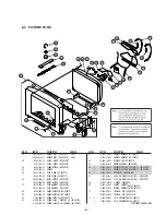
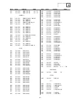
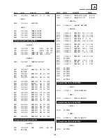
72 

 4-079-355-01  CLIP, DGC (KV-28CS70)


 2-023-248-01  DGC CLIP  (KV-32CS70)

73 

 4-093-607-01  HOLDER, DGC (KV-28CS70)

74 

*A-1071-321-A  VM BOARD, COMPLETE (KV-28CS70)


*A-1055-723-A  VM BOARD, COMPLETE (KV-32CS70)

75 

 4-203-658-01  SPACER, DY (KV-28CS70)


 4-086-199-02  SPACER, DY (KV-32CS70)

76 

 4-202-693-01  HOLDER, HV CABLE (KV-28CS70)


 4-202-554-02  HOLDER, HV CABLE (KV-32CS70)

77    £ 

 1-251-946-21  CAP ASSY, HIGH-VOLTAGE (KV-28CS70)

      £ 

 1-251-374-33  CAP ASSY, HIGH-VOLTAGE (KV-32CS70)

78    £ 

*8-737-794-05  PICTURE TUBE (W66LWS000X) (KV-28CS70)

      £ 

*8-735-217-05  PICTURE TUBE (W76LWN000X) (KV-32CS70)

79 

 4-036-188-01  SCREW, SELF TAPPING (KV-28CS70)


 4-046-765-12  SCREW, TAPPING 7+CROWN WASHER (KV-32CS70)

80 

 4-308-870-00  CLIP, LEAD WIRE

81 

 1-452-014-11  CIRCULAR DISC MAGNET B

82 

 1-452-032-00  MAGNET, DISK

83 

 X-4387-214-1  PERMALLOY, CORRECTION

84 

 3-701-007-00  BAND, BINDING

Summary of Contents for FD Trinitron WEGA KV-32CS70

Page 1: ...RM 947 FR SCC R33A A KV 28CS70E RM 947 ESP SCC R31D A KV 28CS70U RM 932 UK SCC Q84X A MODEL COMMANDER DEST CHASSIS NO KV 28 32CS70 RM 947 KV 32CS70B RM 947 FR SCC Q83X A KV 32CS70E RM 947 ESP SCC R31A A KV 32CS70K RM 947 OIRT SCC Q82N A KV 32CS70U RM 932 UK SCC Q84W A RM 932 ...

Page 2: ...L PARTS LIST 53 CAUTION SHORT CIRCUIT THE ANODE OF THE PICTURE TUBE AND THE ANODE CAP TO THE METAL CHASSIS CRT SHIELD OR THE CARBON PAINTED ON THE CRT AFTER REMOVAL OF THE ANODE CAP WARNING AN ISOLATION TRANSFORMER SHOULD BE USED DURING ANY SERVICE WORK TO AVOID POSSIBLE SHOCK HAZARD DUE TO LIVE CHASSIS THE CHASSIS OF THIS RECEIVER IS DIRECTLY CONNECTED TO THE POWER LINE SAFETY RELATED COMPONENT W...

Page 3: ...to be set to 370 degrees centigrade This requires soldering equipment capable of accurate temperature control coupled with a good heat recovery characteristics For more information on the use of Lead Free Solder please refer to http www sony training com r e b m u n t r a P r e t e m a i D s k r a m e R 9 1 5 0 0 0 4 6 7 m m 3 0 g K 5 2 0 0 2 5 0 0 0 4 6 7 m m 4 0 g K 0 5 0 1 2 5 0 0 0 4 6 7 m m 5...

Page 4: ... 4 0 W 4 9 0 7 S C 2 3 V K W 4 0 W 2 0 1 r o t c e n n o c o r u E n i p 1 2 2 s l a n g i s o e d i V d n a o i d u A r o f s t u p n I B G R r o f s t u p n I s l a n g i s o i d u A d n a o e d i V V T f o s t u p t u O t u O r o t i n o M s n o i s n e m i D 0 7 S C 8 2 V K m m 8 4 5 x 7 1 5 x 4 4 8 x o r p p A 0 7 S C 2 3 V K m m 2 7 5 x 2 6 5 x 3 3 9 x o r p p A t h g i e W 0 7 S C 8 2 V K g...

Page 5: ...pen 13 Ground red 14 Ground blanking 15 _ _ Red input 0 7 3dB 75 ohms positive _ S signal Chroma input 0 3 3dB 75 ohms positive 16 Blanking input Ys signal High state 1 3V Low state 0 0 4V Input impedence 75 ohms 17 Ground video output 18 Ground video input 19 Video output 1V 3dB 75ohms positive sync 0 3V 3 10dB 20 _ _ Video input 1V 3dB 75ohms positive sync 0 3V 3 10dB _ Video input Y S signal 1V...

Page 6: ... The identification of errors within the AE 6B chassis is triggered in one of two ways 1 Busy or 2 Device failure to respond to IIC In the event of one of these situations arising the software will first try to release the bus if busy Failure to do so will report with a continuous flashing LED and then communicate with each device in turn to establish if a device is faulty If a device is found to ...

Page 7: ...the screen Press the OK button to select Yes Language Select Language iv Svenska Norsk English Nederlands Français Italiano iV OK If picture slants please adjust picture rotation Not necessary Adjust now OK continued Do you want to start automatic tuning Yes No OK 8 First Time Operation Switching on the TV and Automatically Tuning 5 The TV starts to automatically search and store all available bro...

Page 8: ... make any adjustments and finally press the OK button to store Effect b v Natural Enhances clarity detail and presence of sound by using the BBE High Definition Sound system v Dynamic BBE High Definition Sound system intensifies clarity and presence of sound for better intelligibility and musical realism v Dolby Virtual Simulates the sound effect of Dolby Surround Pro Logic v Off Flat response Tre...

Page 9: ...as in step 6 b of the section Switching On the TV and Automatically Tuning on page 8 PROGRAMME LABELS The Programme Labels option in the Set Up menu allows you to name a channel using up to five characters letters or numbers To do this 1 After selecting the option press the b button then press the v or V buttons to select the programme number of the channel you wish to name 2 Press b button With t...

Page 10: ...ove Picture Adjustment Mode Personal Contrast Brightness Colour Sharpness Hue Reset OK Set Up Language Country Auto Tuning Programme Sorting Progamme Labels AV Preset Manual Programme Preset Detail Set Up OK Set Up Language Auto Tuning Programme Sorting Progamme Labels AV Preset Manual Programme Preset Detail Set Up OK continued Teletext 17 Teletext GB TELETEXT Index Programme News Sport Weather 2...

Page 11: ...al We recommend you connect your VCR using a Scart lead If you do not have a Scart lead tune in the VCR test signal to the TV programme number 0 by using the Manual Programme Preset option for details of how to manually programme these presets see page 13 step a Refer to your VCR instruction manual to find out the output channel of your VCR Connecting a VCR that supports Smartlink Smartlink is a d...

Page 12: ...ndby indicator is on press the button or a numbered button on the remote control Poor or no picture screen is dark but good sound Using the MENU system select the Picture Adjustment display and select RESET to return to the factory settings No picture or menu information from equipment connected to the Scart socket Check that the optional equipment is on and press the button of the remote control ...

Page 13: ...s forwards Refit the inter connecting leads in their respective purse locks 2 3 Chassis Removal and Refitting 2 2 Service Position Remove the rear cover fixing screws indicated and pull the rear cover backwards away from the set Position the chassis as indicated to access the solder side of the PWB s To gain access to the underside of the boards follow the instructions on page 16 Removal and Repla...

Page 14: ...nsion cable as indicated above The Extender board and extension cable are available as a service part by ordering the part number as indicated 2 6 Service Connector for M Board To A Board From M Board Extender Board Assembly A 1642 293 A 2 7 Wire Dressing Ensure that wires do not touch heatsinks and high temperature hotspots All wires must be kept at a minimum distance of 20mm away from the EHT le...

Page 15: ...ll interconnecting leads from the Deflection yoke neck assy degaussing coils and CRT grounding strap 3 Remove the C Board from the CRT 4 Remove the chassis assembly 5 Loosen the Neck assembly fixing screw and remove 6 Loosen the Deflection yoke fixing screw and remove 7 Place the set with the CRT face down on a cushion and remove the Degaussing Coil holders 8 Remove the Degaussing Coils 9 Remove t...

Page 16: ...o be removed This is performed by cutting the gates with a sharp wire cutter at the locations indicated by the arrows Note There are 2 plates fitted to the main bracket Only remove the necessary plate to gain access to the printed wiring board 2 REFITTINGTHE PLATES Because the plates differ in size it is important that the correct plates are refitted in their original location Please note that the...

Page 17: ...o Green and verify the condition 6 When the position of the deflection yoke has been determined fasten the deflection yoke with the screws 7 If the beam does not land correctly in all the corners use a magnet to correct it See Fig 3 4 When complete readjustment is necessary or a new picture tube is installed carry out the following adjustments Unless there are specific instructions to the contrary...

Page 18: ...e each other The movement of the magnets interact with each other and so the respective dot position should be monitored while carrying out this adjustment Use the H STAT VR to adjust the Red Green and Blue dots so that they coincide at the centre of the screen by moving the dots in the horizontal direction G B R G B R G B R G B R G B R G B R 3 2 Convergence Preparation Before starting this adjust...

Page 19: ...p and Down a small amount will balance the upper and lower pin adjustment 3 Re install the deflection yoke spacers Ensure 4 DY spacers are reinserted Screen Corner Convergence a b d Permalloy Assy c Install the permalloy assembly for the area that needs correcting X 4387 214 1 Convergence adjustment with permalloy APH circuit harness Deflection Yoke TLH Piece H Trap YCH TLV Deflection Yoke TLH Pie...

Page 20: ... minimum 3 Apply 165V DC from an external power supply to the R G and B cathodes of the CRT 4 Whilst watching the picture adjust the G2 control SCREEN located on the flyback transformer to the point just before the flyback return lines disappear 1 Input an all white signal from the pattern generator 2 Set the TV set or operation in Service Mode See Page 21 3 Select Service from the on screen menu ...

Page 21: ...e main power switch and enter into the stand by mode 2 Press the following sequence of buttons on the Remote Commander A M A R O N A P H H T D I W R O H L H T D I W R O H H S O P R O H L S O P R O H H P I L P P A N L P I L P P A N H C S O P C S H L C S O P C S H L E D N A L B N E L N A L B L O P N A L B H 1 G E S H L 1 G E S H H 2 G E S H L 2 G E S H H 3 G E S H L 3 G E S H H 4 G E S H L 4 G E S H...

Page 22: ... menu display and press Right Arrow 5 The Service menu will appear on the screen 6 Adjust the Sub Colour sothat the Cyan Magenta and Blue colour bars are of equal levels as indicated below Same Level B Out Waveform 1 Input a Monoscope pattern 2 Set the TV set or operation in Service Mode See Page 21 3 Select Service from the on screen menu display and press Right Arrow 4 The Service menu will appe...

Page 23: ... s t e S 7 0 e d o m g n i e g A 8 0 n o i t i d n o C g n i p p i h S 1 1 t n e m t s u j d a e r u t c i p b u S 2 1 t n e m t s u j d a r u o l o c b u S 3 1 t n e m t s u j d a s s e n t h g i r B b u S 4 1 t n e m t s u j d a n o i t i s o P H t x e T 5 1 t s e T l i o C n o i t a t o R 6 1 0 5 l e v e l e r u t c i P 9 1 e l b a s i D e l b a n E e d o M y r o t c a F 1 2 R K E D A n o i t a...

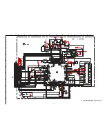
Page 24: ...1 1 3 2 6 J4501 J4500 H6 FRONT AV INPUT HEADPHONE AND CONTROL SWITCHES 5 R 9 L Y CVBS KEY 6 4 1 TO A BOARD CN2000 L IN V L R 3 1 2 4 2 CHROMA SWITCH S4502 SWITCH S4501 SWITCH S4500 RIGHT OUT CN2501 IC2000 AUDIO PROCESSOR A 1 2 VIDEO AND AUDIO PROCESSORS AUDIO OUTPUT VERTICAL DEFLECTION 67 IF INI SCL 3 SDA 37 56 SC1 OUT L SC1 IN L 2 SC1 OUT R 57 SC1 IN R 36 27 28 30 TO SPEAKERS SPEAKER OUT R SPEAKE...

Page 25: ...4 D6032 1 1 2 3 Q6104 Q6105 1 3 1 2 1 2 4 3 C6018 SWITCH Q6005 Q6010 OCP 12 C6015 CN8611 6 4 5 3 2 1 V TO A BOARD 1 2 CN8001 V DY V DY DY ASSY V DY H DY H DY H DY 1 2 4 200V T8800 V H H H 1 3 CN8612 V V CN8810 TO A BOARD 1 2 CN5801 2 3 COMPARATOR IC8100 1 4 7 8 5 3 4 H CENTRE M PIN CONT 2 3 4 5 6 7 8 CN8620 MP PARA E W H LIN H DRIVE AFC PULSE ABL X RAY PROTECT Q8201 Q8202 Q8118 T8802 HDT 1 4 2 T88...

Page 26: ... 1 BLOCK DIAGRAMS 3 A 0 A 1 A 2 A 3 A 4 A 5 A 6 A 7 A 8 A 9 A 10 A 11 A 12 A 13 A 14 A 15 A 16 A 17 CN0001 IC0002 MICRO CONTROLLER M MICRO PROCESSOR IC0001 NVM MEMORY 7 8 SCL 6 5 9 SDA 28 24 LED LED 76 10 SIRCS SIRCS AGC AGC 22 40 MODE 3 AGC 29 25 OVP 80 11 GROUP DELAY 24 23 OCP OVP OCP 59 15 COINCIDENCE GROUP DELAY 17 13 MAIN RY OCP FLAG 16 14 DGC RY COINCIDENCE 46 20 B TEXT B TEXT 47 19 G TEXT G...

Page 27: ...iagram Audio Amp Scart Connector Page 1 7 F 2 5 3 4 1 MICRO A 2 6 3 6 6 6 SCART AUDIO A 2 6 VIDEO A 2 6 3 6 5 6 MUTE A 2 6 A1 7 AUDIO AMP SCART CONNECTOR COMPONENTS MARKED AS XX ARE NOT FITTED ON THIS MODEL A 28 32CS70 XX 9V REG 5V REG 3 3V REG 1 8V REG 5A 6 4502 IF AGC 4P F5 ...

Page 28: ...11 28 A Board Schematic Diagram Audio Processor Page 2 7 COMPONENTS MARKED AS XX ARE NOT FITTED ON THIS MODEL A 28 32CS70 MICRO A 1 6 3 6 6 6 VIDEO A 1 6 3 6 5 6 MUTE A 1 6 YUV 100 A 3 6 4 6 A2 7 AUDIO PROCESSOR MSP3411G QA B11 SCART AUDIO A 1 6 4501 ...

Page 29: ...Page 3 7 COMPONENTS MARKED AS XX ARE NOT FITTED ON THIS MODEL A3 7 RGB H DEFLECTION VIDEO A 1 6 2 6 5 6 MICRO A 1 6 2 6 6 6 YUV 100 A 2 6 4 6 H CENTRE A 4 6 V PROT A 4 6 A 28 32CS70 H LIN A 4 6 VDN OUT A 4 6 VDP OUT A 4 6 ABL A 4 6 DF A 4 6 1 16V CN5802 XX DEFLECTION CONTROL CCT 12V REG 10K 6 8K 7P ...

Page 30: ...eflection Rotation Coil Page 4 7 H CENTRE A 3 6 YUV 100 A 2 6 3 6 H SYNC VPROT A 3 6 H LIN A 3 6 ABL A 3 6 DF A 3 6 VDP OUT A 3 6 VDN OUT A 3 6 COMPONENTS MARKED AS XX ARE NOT FITTED ON THIS MODEL A 28 32CS70 LA6500 FA XX STV9379A A4 7 VERTICAL DEFLECTION ROTATION COIL DEFLECTION CONTROL CCT ...

Page 31: ...d Schematic Diagram Colour Decoder Video Switch Page 5 7 VSYNC A 6 6 HSYNC A 6 6 CVBS TXT A 6 6 RESET A 6 6 VIDEO RF A 6 6 VIDEO A 1 6 2 6 3 6 A5 7 COLOUR DECODER VIDEO SWITCH COMPONENTS MARKED AS XX ARE NOT FITTED ON THIS MODEL VSP9402A A32GEG 10 50V A 28 32CS70 ...

Page 32: ...1 32 A Board Schematic Diagram Interface Page 6 7 VSYNC A 5 6 CVBS TXT A 5 6 HSYNC A 5 6 RESET A 5 6 VIDEO RF A 5 6 A6 7 INTERFACE COMPONENTS MARKED AS XX ARE NOT FITTED ON THIS MODEL MICRO A 1 6 2 6 3 6 TO M BOARD A 28 32CS70 5V REG 3 3V REG 100PF 50V ...

Page 33: ...A B C D E F G H I J K L M N 1 2 3 4 5 6 7 8 9 10 11 33 A Board Schematic Diagram Tuner Page 7 7 COMPONENTS MARKED AS XX ARE NOT FITTED ON THIS MODEL TUNER 2SD601A A 28 32CS70 ...

Page 34: ...A B C D E F G H I J K L M N 1 2 3 4 5 6 7 8 9 10 11 34 A Printed Wiring Board Conductor side A ...

Page 35: ...A B C D E F G H I J K L M N 1 2 3 4 5 6 7 8 9 10 11 35 A Printed Wiring Board Conductor side B ...

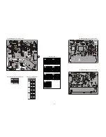
Page 36: ...C I 3 B 2 0 2 6 C I 6 I 1 0 3 5 Q 5 C 2 1 1 0 D 4 M 1 0 0 3 D 7 M 3 1 0 3 D 4 M 4 2 0 3 D 4 M 1 0 2 5 D 2 E 7 0 8 5 D 7 F 1 0 2 5 C I 4 C 3 0 2 6 C I 6 J 6 0 3 5 Q 4 E 3 1 1 0 D 5 M 3 0 0 3 D 7 M 5 1 0 3 D 4 M 6 2 0 3 D 2 M 5 0 3 5 D 6 D 0 0 2 6 D 6 J 0 0 3 5 C I 4 E 5 0 2 6 C I 5 D 4 0 4 5 Q 4 F 6 0 0 1 D 0 1 M A Board LocationTable B Side f e R s g d f e R e b c f e R e b c f e R e b c f e R e b...

Page 37: ... 10uH L4501 10uH L4502 S4500 S4501 S4502 1 4W 6 8k R4510 1 4W 3 3k R4511 1 4W 15k R4512 1 4W 10k R4513 5 R4515 1 4W 1 5k R4514 5 L5400 1 2 3 4 5 6 7 CN4500 XX VOL VOL PRESET VIDEO PROG PROG GND 1 2 3 4 5 6 7 8 9 WHT 9P CN4501 KEY C GND Y CVBS GND L GND GND R 1 2 3 4 5 6 WHT 6P CN4502 WOOFERMUTE R IN R OUT GND L OUT L IN J4501 3 4 1 2 L R V S J4500 H6 H6 28 32CS70 COMPONENTS MARKED AS XX ARE NOT FI...

Page 38: ...r is directly connected to the power line H6 PrintedWiring Board Conductor side G Board Semiconductor LocationTable E D O I D 2 1 0 6 D 3 E 4 3 0 6 D 2 E 8 0 0 6 Q 4 D 2 0 0 6 D 3 A 3 1 0 6 D 3 A C I 9 0 0 6 Q 4 E 3 0 0 6 D 4 G 5 1 0 6 D 2 E 1 0 0 6 C I 5 G 0 1 0 6 Q 2 B 4 0 0 6 D 4 G 3 2 0 6 D 3 H R O T S I S N A R T 4 1 0 6 Q 2 J 8 0 0 6 D 3 G 0 3 0 6 D 4 G 3 0 0 6 Q 1 M 1 0 1 6 Q 1 L 9 0 0 6 D ...

Page 39: ...A B C D E F G H I J K L M N 1 2 3 4 5 6 7 8 9 10 11 39 G Board Schematic Diagram Power Supply D6035 5MM FB6006 5MM FB6005 5MM ...

Page 40: ...A B C D E F G H I J K L M N 1 2 3 4 5 6 7 8 9 10 11 40 D Board Schematic Diagram Deflection C8119 0 1 D8860 RD15ESB2 5600PF 1 2V 0 56 250V 5P 7P 8 2K XX ...

Page 41: ... f e R s e g b d c f e R s e g b d c 0 0 1 8 Q 0 6 0 6 3 0 1 1 8 Q 4 2 1 3 0 8 2 1 8 Q 4 3 5 1 9 8 1 0 8 8 Q 0 4 0 7 4 6 1 0 1 8 Q 0 6 0 3 4 3 1 1 8 Q 3 0 2 0 9 8 2 3 1 8 Q 0 0 4 3 2 0 8 8 Q 0 4 0 2 3 7 2 0 1 8 Q 0 3 0 3 4 5 1 1 8 Q 6 8 9 8 0 5 3 1 8 Q 6 2 2 3 9 8 7 0 8 8 Q 0 3 6 0 3 0 1 8 Q 0 4 0 9 8 8 1 1 8 Q 0 0 0 5 6 3 1 8 Q 5 2 8 1 0 8 1 8 8 Q 0 0 0 5 4 0 1 8 Q 0 4 0 1 3 9 1 1 8 Q 7 0 4 1 0 7...

Page 42: ... C7355 400V C7304 1 35V 47 C7350 250V 47 C7380 1 2 3 4 5 6 7 8 9 BLK CN7301 9P R R G G B B GND 12V IK 1 4W 1k R7390 C7383 XX 1 10W 1 8k R7391 1 10W 680 R7392 6p C7384 C7385 8p 50V 1 10W 1 5k R7393 1 4W 1k R7394 C7386 XX 1 10W 1 8k R7395 1 10W 680 R7396 50V 6p C7387 1 10W 1 5k R7397 C7388 8p 50V 1 4W 1k R7398 C7389 XX 1 10W 1 8k R7399 1 10W 680 R7374 50V 6p C7390 1 10W 1 5k R7373 C7391 8p 50V 10uH ...

Page 43: ... 2 5 3 7 Q 0 0 8 3 3 5 3 7 Q 0 0 8 3 4 5 3 7 Q 8 9 1 1 2 1 0 5 5 3 7 Q 0 0 8 3 C Board Semiconductor VoltageTable e l b a T e g a t l o V C I o N f e R o N n i P V e g a t l o V 0 0 3 7 C I 1 9 3 3 8 3 5 5 7 6 0 0 2 7 0 4 1 8 3 5 1 9 0 4 1 5 2 3 7 C I 1 9 3 3 8 3 5 7 7 6 0 0 2 7 0 4 1 8 3 5 1 9 0 4 1 0 5 3 7 C I 1 9 3 3 8 3 5 5 7 6 0 0 2 7 9 3 1 8 8 4 1 9 8 3 1 C Board IC Voltage Table M Printed W...

Page 44: ...A B C D E F G H I J K L M N 1 2 3 4 5 6 7 8 9 10 11 44 M Board Schematic Diagram Micro Processor ...

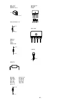
Page 45: ...A LM318P LM358N LM393DT LM393N M24C16 MN6T A LM78L05ACZ MSP3411G QA B10 8 7 6 5 1 3 4 2 IN GND OUT 68 61 60 1 52 44 43 35 27 26 18 10 9 TOP VIEW NJM3404AD W UPC4558G2 TOP VIEW 1 4 8 5 PQ30RV11 1 1 V IN 2 V OUT 3 GND 4 ON OFF CONTROL 2 3 4 PST573IMT 1 3 2 Vcc Out Gnd 1 2 3 SAA5665HL M1D 0358 SDA9488X B23GEG 1 100 25 26 50 51 75 76 1 14 15 28 SBX3081 51 30 STV9379 7 1 ...

Page 46: ... SPA07N60C2 2SA2005 2SC5511 DTA144EK DTC144TKA T146 2SA1162 G DTA144ESA 2SA933AS QT 2SC2785 HFE B C E B C E C B E L7809CV LSY STP5NB40FP STP5NB40 030Y 2SC5698 CA 2S5696 SONY CA MSB709 RT1 MSD601 RST1 M1MA152WA T1 UN2111 UN213 2SK2036 TE85L E RB705D SE135N LF4 2 1 3 1 3 2 1 2 3 1 V OUT SENSE 2 COLLECTOR 3 GND 2SA1837 LBS2S0N E C B 2SB734 34 1 2 3 ...

Page 47: ...DE ANODE TLHK5190 FBIU4D7MA B RBV 406B S1VB40 CATHODE ANODE MTZJ T 77 22 RD15ES B2 RD39ES B2 RD5 6ESB2 1SS119 25 1SS133T 77 GS1B460 45 D2S4MTA1 BYV98 200 RAS 15 12 CATHODE ANODE D1NL20U EGP20G EL1Z GP08D UF4005PKG23 CATHODE ANODE BAS316 115 MMDL914T1 UDZSTE 176 2B CATHODE ANODE ...

Page 48: ...OP AMP 30K 30K 60K 5 5 IC BLOCK DIAGRAMS 4 3 2 6 7 1 5 Vsense Remote DVLD Internal OFF Latch Centre Osc SS F B Timer TSD OCP Control Logic Level Shift Sel 34v ref 5v 15v 8v Driver Reg 10v 18 8 14 16 15 10 12 11 9 A BOARD IC6202 IC6205 BA033T BA12T G BOARD IC6001 MCZ3001D A BOARD IC2500 TDA7497 ...

Page 49: ...face 25 23 65 68 1 3 4 5 7 6 48 50 51 47 30 34 31 28 33 37 36 DEMODULATOR A BOARD IC2000 MSP3411G 1 5 4 3 8 7 2 6 9 G BOARD IC6003 SE135N LF4 FLYBACK GENERATOR THERMAL PROTECTION 2 6 3 5 4 7 1 POWER AMPLIFIER A BOARD IC5400 STV9379A 1 2 3 7 5 6 A BOARD IC5301 IC5302 LM393N A BOARD IC5300 LM358N 1 2 3 4 6 5 7 8 ...

Page 50: ...00 179 A G BOARD COMPLETE 9 8 598 623 10 TUNER FSS BTP AC421 KV 28CS70B E KV 32CS70B E K 8 598 624 10 TUNER FSS BTP AU621 KV 28CS70U KV 32CS70U 10 A 1055 725 A A BOARD COMPLETE KV 28CS70B A 1062 981 A A BOARD COMPLETE KV 28CS70E A 1063 011 A A BOARD COMPLETE KV 28CS70U A 1055 720 A A BOARD COMPLETE KV 32CS70B A 1060 570 A A BOARD COMPLETE KV 32CS70E A 1060 570 A A BOARD COMPLETE KV 32CS70K A 1060 ...

Page 51: ...EW 4x16 TAPPING P KV 28CS70 4 058 870 01 SCREW 4x16 W P TAPPING KV 32CS70 67 73 80 81 82 83 84 51 74 58 52 66 65 54 68 59 53 55 56 57 60 61 62 64 69 70 71 70 75 76 77 78 79 63 63 72 72 71 62 4 103 133 01 CHASSIS BRACKET KV 28CS70 4 102 519 01 CHASSIS BRACKET KV 32CS70 63 4 206 160 01 SUPPORT CRT KV 28CS70 64 4 204 666 01 SHEET BLOTTING KV 32CS70 65 8 451 540 11 DEFLECTION YOKE Y28VECP L KV 28CS70 ...

Page 52: ...76 4 202 693 01 HOLDER HV CABLE KV 28CS70 4 202 554 02 HOLDER HV CABLE KV 32CS70 77 1 251 946 21 CAP ASSY HIGH VOLTAGE KV 28CS70 1 251 374 33 CAP ASSY HIGH VOLTAGE KV 32CS70 78 8 737 794 05 PICTURE TUBE W66LWS000X KV 28CS70 8 735 217 05 PICTURE TUBE W76LWN000X KV 32CS70 79 4 036 188 01 SCREW SELF TAPPING KV 28CS70 4 046 765 12 SCREW TAPPING 7 CROWN WASHER KV 32CS70 80 4 308 870 00 CLIP LEAD WIRE 8...

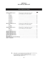
Page 53: ... 28CS70 63 KV 32CS70 63 KV 28CS70B 63 KV 28CS70E 63 KV 28CS70U 63 KV 32CS70B 64 KV 32CS70E 64 KV 32CS70K 64 KV 32CS70U 64 VM BOARD COMMON Parts List Parts common to all models listed in this manual 64 Model Parts that belong only to the model specified KV 28CS70 65 KV 32CS70 65 D BOARD COMMON Parts List Parts common to all models listed in this manual 65 Model Parts that belong only to the model s...

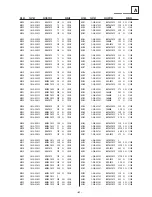
Page 54: ... 00 50V C2010 1 162 964 11 CERAMIC CHIP 0 001UF 10 00 50V C2011 1 162 962 11 CERAMIC CHIP 470PF 10 00 50V C2012 1 162 962 11 CERAMIC CHIP 470PF 10 00 50V C2013 1 162 962 11 CERAMIC CHIP 470PF 10 00 50V C2014 1 164 346 11 CERAMIC CHIP 1UF 16V C2015 1 163 021 91 CERAMIC CHIP 0 01UF 10 00 50V C2016 1 162 962 11 CERAMIC CHIP 470PF 10 00 50V C2018 1 162 962 11 CERAMIC CHIP 470PF 10 00 50V C2019 1 164 3...

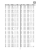
Page 55: ...1 164 222 91 CERAMIC CHIP 0 22UF 25V C3215 1 164 222 91 CERAMIC CHIP 0 22UF 25V C3216 1 164 222 91 CERAMIC CHIP 0 22UF 25V C3217 1 164 222 91 CERAMIC CHIP 0 22UF 25V C3218 1 164 222 91 CERAMIC CHIP 0 22UF 25V C3219 1 164 222 91 CERAMIC CHIP 0 22UF 25V C3220 1 164 222 91 CERAMIC CHIP 0 22UF 25V C3221 1 164 222 91 CERAMIC CHIP 0 22UF 25V C3222 1 164 222 91 CERAMIC CHIP 0 22UF 25V C3223 1 164 222 91 ...

Page 56: ...AMIC CHIP 0 047UF 10 00 16V C5897 1 162 970 11 CERAMIC CHIP 0 01UF 10 00 25V C5898 1 162 964 11 CERAMIC CHIP 0 001UF 10 00 50V D1 A C5899 1 107 823 11 CERAMIC CHIP 0 47UF 10 00 16V C6200 1 126 933 11 ELECT 100UF 20 00 16V C6201 1 126 935 11 ELECT 470UF 20 00 16V C6202 1 126 933 11 ELECT 100UF 20 00 16V C6203 1 126 925 91 ELECT 470UF 20 00 10V C6204 1 126 933 11 ELECT 100UF 20 00 16V C6205 1 126 92...

Page 57: ...005AD IC5103 8 752 072 94 IC CXA1875AM T4 F4 A C7070 1 162 919 11 CERAMIC CHIP 22PF 5 00 50V C7071 1 162 919 11 CERAMIC CHIP 22PF 5 00 50V CONNECTOR CN0101 1 823 330 11 CONNECTOR BOARD TO BOARD 40P CN0102 1 564 520 11 PLUG CONNECTOR 5P CN0103 1 817 035 61 PLUG CONNECTOR 4P CN1000 1 417 319 11 CONNECTOR SQUARE TYPE 21P CN2000 1 564 512 11 PLUG CONNECTOR 9P CN2500 1 816 974 51 PLUG CONNECTOR 3P CN25...

Page 58: ... 295 91 SHORT CHIP 0 L3012 1 216 295 91 SHORT CHIP 0 L3200 1 412 006 31 INDUCTOR 10UH L3202 1 412 006 31 INDUCTOR 10UH L3203 1 412 006 31 INDUCTOR 10UH L3206 1 412 006 31 INDUCTOR 10UH L3208 1 412 006 31 INDUCTOR 10UH L3209 1 216 864 11 SHORT CHIP 0 L3300 1 412 006 31 INDUCTOR 10UH L5300 1 406 989 21 INDUCTOR 10MH L5301 1 406 989 21 INDUCTOR 10MH L5400 1 412 524 11 INDUCTOR 8 2UH L5896 1 216 864 1...

Page 59: ...AL CHIP 470 5 1 10W R2011 1 216 049 11 RES CHIP 1K 5 1 10W R2014 1 216 049 11 RES CHIP 1K 5 1 10W R2015 1 216 295 91 SHORT CHIP 0 R2017 1 216 853 11 METAL CHIP 470K 5 1 10W R2018 1 216 295 91 SHORT CHIP 0 Q3302 8 729 010 05 TRANSISTOR MSB709 RT1 Q3500 8 729 028 28 TRANSISTOR 2SK2036 TE85L Q3501 8 729 028 28 TRANSISTOR 2SK2036 TE85L Q5100 8 729 010 05 TRANSISTOR MSB709 RT1 Q5101 8 729 010 29 TRANSI...

Page 60: ...1 RES CHIP 100 5 1 10W R3019 1 216 022 00 RES CHIP 75 5 1 10W R2020 1 216 853 11 METAL CHIP 470K 5 1 10W R2023 1 216 853 11 METAL CHIP 470K 5 1 10W R2026 1 216 853 11 METAL CHIP 470K 5 1 10W R2029 1 216 853 11 METAL CHIP 470K 5 1 10W R2032 1 216 853 11 METAL CHIP 470K 5 1 10W R2035 1 216 853 11 METAL CHIP 470K 5 1 10W R2038 1 216 853 11 METAL CHIP 470K 5 1 10W R2041 1 216 853 11 METAL CHIP 470K 5 ...

Page 61: ... METAL CHIP 22K 0 5 1 10W R5103 1 218 833 11 METAL CHIP 270 0 5 1 10W R5107 1 208 814 91 METAL CHIP 22K 0 5 1 10W R5111 1 208 814 91 METAL CHIP 22K 0 5 1 10W R5112 1 218 875 11 METAL CHIP 15K 0 5 1 10W R5118 1 249 411 11 CARBON 330 5 1 4W R5119 1 216 844 11 METAL CHIP 82K 5 1 10W R5122 1 216 821 11 METAL CHIP 1K 5 1 10W R5125 1 216 836 11 METAL CHIP 18K 5 1 10W R5126 1 249 406 11 CARBON 120 5 1 4W...

Page 62: ...3 11 METAL CHIP 10K 5 1 10W R5882 1 216 833 11 METAL CHIP 10K 5 1 10W R5884 1 216 841 11 METAL CHIP 47K 5 1 10W R5885 1 216 809 11 METAL CHIP 100 5 1 10W R5887 1 216 809 11 METAL CHIP 100 5 1 10W R5888 1 216 809 11 METAL CHIP 100 5 1 10W R5889 1 208 806 11 METAL CHIP 10K 0 5 1 10W R5892 1 216 833 11 METAL CHIP 10K 5 1 10W R5895 1 216 833 11 METAL CHIP 10K 5 1 10W R5898 1 216 832 11 METAL CHIP 8 2K...

Page 63: ... CHIP 33 5 1 10W FILTER SF1001 1 795 617 11 SAW FILTER CRYSTAL X1001 1 767 704 11 VIBRATOR CRYSTAL X2000 1 760 628 11 VIBRATOR CRYSTAL X3200 1 781 946 21 VIBRATOR CRYSTAL X5800 1 767 127 11 VIBRATOR CERAMIC A Board Variant Parts KV28CS70 CAPACITOR C5320 1 129 716 00 FILM 0 015UF 5 00 630V C5321 1 136 347 11 FILM 0 0047UF 5 00 630V C5853 1 162 970 11 CERAMIC CHIP 0 01UF 10 00 25V C5868 1 163 129 00...

Page 64: ...T 470UF 20 00 16V C7413 1 126 935 11 ELECT 470UF 20 00 16V C7414 1 107 652 11 ELECT 10UF 20 00 250V C7415 1 107 363 91 MYLAR 0 0068UF 10 00 200V C7418 1 163 021 91 CERAMIC CHIP 0 01UF 10 00 50V C7421 1 163 251 11 CERAMIC CHIP 100PF 5 00 50V C7501 1 130 495 00 MYLAR 0 1UF 5 00 50V CONNECTOR CN7442 1 564 510 11 PLUG CONNECTOR 7P CN7443 1 564 506 11 PLUG CONNECTOR 3P CN7444 1 770 747 11 CONNECTOR BOA...

Page 65: ...M 0 1UF 5 00 50V C8101 1 136 497 81 FILM 0 1UF 5 00 50V C8102 1 136 497 81 FILM 0 1UF 5 00 50V C8103 1 115 416 11 CERAMIC CHIP 0 001UF 5 00 25V C8104 1 115 416 11 CERAMIC CHIP 0 001UF 5 00 25V C8105 1 126 947 11 ELECT 47UF 20 00 35V C8108 1 162 970 11 CERAMIC CHIP 0 01UF 10 00 25V C8109 1 126 947 11 ELECT 47UF 20 00 35V C8113 1 162 970 11 CERAMIC CHIP 0 01UF 10 00 25V C8114 1 126 964 11 ELECT 10UF...

Page 66: ...D15ESB2 D8818 8 719 109 89 DIODE RD5 6ESB2 D8819 8 719 050 38 DIODE M1MA152WK T1 D8820 8 719 081 97 DIODE MMDL914T1 D8851 8 719 970 87 DIODE ERA38 06 D8860 8 719 110 41 DIODE RD15ESB2 FERRITE BEAD FB8806 1 535 303 00 LEAD JUMPER 5 0MM FB8807 1 535 303 00 LEAD JUMPER 5 0MM IC IC8100 8 759 659 67 IC LA6393DLL IC8101 8 759 659 67 IC LA6393DLL IC8102 8 759 638 79 IC NJM3404AD W IC8103 8 759 659 67 IC ...

Page 67: ... R8137 1 208 822 11 METAL CHIP 47K 0 5 1 10W R8138 1 208 822 11 METAL CHIP 47K 0 5 1 10W R8139 1 208 822 11 METAL CHIP 47K 0 5 1 10W R8140 1 216 825 11 METAL CHIP 2 2K 5 1 10W R8143 1 216 825 11 METAL CHIP 2 2K 5 1 10W R8145 1 216 825 11 METAL CHIP 2 2K 5 1 10W R8146 1 208 790 11 METAL CHIP 2 2K 0 5 1 10W R8153 1 216 295 91 SHORT CHIP 0 R8162 1 216 821 11 METAL CHIP 1K 5 1 10W R8163 1 216 833 11 M...

Page 68: ...C8815 1 117 633 11 FILM 3900PF 3 00 1 2KV C8825 1 117 633 11 FILM 3900PF 3 00 1 2KV C8827 1 119 858 11 FILM 0 068UF 5 00 250V C8840 NOT FITTED C8851 1 162 131 11 CERAMIC 220PF 10 00 2KV C8853 1 136 535 91 FILM 0 0018UF 5 00 630V C8860 NOT FITTED C8869 NOT FITTED DIODE D8129 NOT FITTED D8198 NOT FITTED D8856 NOT FITTED D8857 NOT FITTED D8858 NOT FITTED INDUCTOR LF8851 1 406 674 11 INDUCTOR 3 3MH TR...

Page 69: ...91 METAL CHIP 22K 0 5 1 10W R8127 1 218 859 11 METAL CHIP 3 3K 0 5 1 10W R8141 1 216 839 11 METAL CHIP 33K 5 1 10W R8142 1 216 829 11 METAL CHIP 4 7K 5 1 10W R8144 1 216 845 11 METAL CHIP 100K 5 1 10W R8149 1 216 828 11 METAL CHIP 3 9K 5 1 10W R8150 1 218 867 11 METAL CHIP 6 8K 0 5 1 10W R8154 1 216 818 11 METAL CHIP 560 5 1 10W R8155 1 216 065 91 RES CHIP 4 7K 5 1 10W R8158 1 208 798 11 METAL CHI...

Page 70: ... SW CAPACITOR C6001 1 165 528 11 MYLAR 0 1UF 10 275V C6002 1 165 528 11 MYLAR 0 1UF 10 275V C6003 1 119 899 51 CERAMIC 1000PF 10 00 250V C6004 1 119 899 51 CERAMIC 1000PF 10 00 250V C6005 1 126 965 91 ELECT 22UF 20 00 50V C6006 1 117 753 11 ELECT BLOCK 470UF 20 00 450V C6007 1 126 964 11 ELECT 10UF 20 00 50V C6008 1 126 963 11 ELECT 4 7UF 20 00 50V C6010 1 136 497 81 FILM 0 1UF 5 00 50V C6011 1 16...

Page 71: ... 100 5 1 4W R6038 1 208 830 11 METAL CHIP 100K 0 5 1 10W R6039 1 208 830 11 METAL CHIP 100K 0 5 1 10W R6040 1 208 814 91 METAL CHIP 22K 0 5 1 10W R6042 1 216 295 91 SHORT CHIP 0 R6045 1 216 639 11 METAL CHIP 330 0 5 1 10W R6047 1 216 681 11 METAL CHIP 18K 0 5 1 10W R6048 1 215 481 00 METAL 330K 1 1 4W R6049 1 208 805 11 METAL CHIP 9 1K 0 5 1 10W R6050 1 208 758 11 METAL CHIP 100 0 5 1 10W R6054 1 ...

Page 72: ...3 1 216 025 11 RES CHIP 100 5 1 10W R0011 1 216 025 11 RES CHIP 100 5 1 10W R0014 1 216 081 00 RES CHIP 22K 5 1 10W R0016 1 216 025 11 RES CHIP 100 5 1 10W R0017 1 216 093 91 RES CHIP 68K 5 1 10W R0018 1 216 025 11 RES CHIP 100 5 1 10W R0019 1 216 073 91 RES CHIP 10K 5 1 10W R0020 1 216 049 11 RES CHIP 1K 5 1 10W R0022 1 216 809 11 METAL CHIP 100 5 1 10W R0023 1 216 097 11 RES CHIP 100K 5 1 10W R0...

Page 73: ...163 009 91 CERAMIC CHIP 0 001UF 10 00 50V C7354 1 126 933 11 ELECT 100UF 20 00 16V C7355 1 107 967 11 ELECT 1UF 20 00 400V C7356 1 136 207 11 MYLAR 0 047UF 5 00 630V C7358 1 162 909 11 CERAMIC CHIP 4PF 0 25PF 50V C7359 1 163 035 00 CERAMIC CHIP 0 047UF 50V C7360 1 163 247 91 CERAMIC CHIP 68PF 5 00 50V C7378 1 162 116 00 CERAMIC 680PF 10 00 2KV C7379 1 162 114 00 CERAMIC 0 0047UF 2KV C7380 1 107 65...

Page 74: ...R 20 0MM R7389 1 247 881 00 CARBON 120K 5 1 4W R7390 1 249 417 11 CARBON 1K 5 1 4W R7391 1 216 824 11 METAL CHIP 1 8K 5 1 10W R7392 1 216 819 11 METAL CHIP 680 5 1 10W R7393 1 216 823 11 METAL CHIP 1 5K 5 1 10W R7394 1 249 417 11 CARBON 1K 5 1 4W R7395 1 216 824 11 METAL CHIP 1 8K 5 1 10W R7396 1 216 819 11 METAL CHIP 680 5 1 10W R7397 1 216 823 11 METAL CHIP 1 5K 5 1 10W R7398 1 249 417 11 CARBON...

Page 75: ...R FSS BTP AU621 KV 28CS70U KV 32CS70U 1 453 340 41 TRANSFORMER ASSY FLYBACK NX 4522 Z2B4 1 424 855 11 COIL CHOKE 29MMH 1 825 859 11 LOUDSPEAKER 5 5X15CM 1 825 860 11 WOOFER ASSY 8 451 540 11 DEFLECTION YOKE Y28VECP L KV 28CS70 1 451 575 11 DEFLECTION YOKE Y32VECP T KV 32CS70 8 453 021 21 NECK ASSY NA2919 M2 1 452 363 11 COIL NA ROTATION RT 200 KV 28CS70 1 419 896 11 COIL NA ROTATION RT 200 KV 32CS...

Page 76: ...re modules Please contact your local Sony Service organisation for the latest information Read restore and compare NVM contents via the I2C bus Acknowledge check of all I2C devices in the TV set Read Error Codes emulation of the Error Reader tool Remote Commander emulation User programmable Functional Check through Infrared Fast and documented Test Mode setting of all Sony TV chassis Partnumbers T...

Reviews: