- 21 -
Sub Colour Adjustment
1.
Receive a PAL colour bar signal.
2.
Connect an oscilloscope to Pin 6 of CN7001 [A Board].
3.
Program the Remote Commander for operation in Service Mode.
[ See Page 20 ].
4.
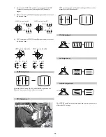
Adjust the ‘Sub Colour’ [ Using ‘VIDEO’ ‘VIDEO’ ‘12’ ] so
that the Cyan, Magenta and Blue colour bars are of equal levels
as indicated below.
Same Level
B-Out Waveform
Sub Brightness Adjustment
1.
Input a Monoscope pattern.
2.
Program the Remote Commander for operation in Service Mode.
[ See Page 20 ].
3.
Press ‘VIDEO’ ‘VIDEO’ 13 on the Remote Commander.
4.
Adjust the ‘Sub-Brightness’ data so that there is barely a
difference between the 0 IRE and 10 IRE signal levels.
1.
Input a video signal that contains a small 100% white area on a
black background.
2.
Connect an digital voltmeter to Pin 10 of J7378 [C Board].
3.
Program the Remote Commander for operation in Service Mode.
[ See Page 20 ].
4.
Adjust the Sub-Contrast [ Using ‘VIDEO’ ‘VIDEO’ ‘11’ ] to
obtain a voltage of 105 +/- 5V.
Sub Contrast Adjustment
U
N
E
M
R
O
R
R
E
2
0
E
3
0
E
4
0
E
5
0
E
6
0
E
7
0
E
8
0
E
9
0
E
0
1
E
1
1
E
2
1
E
3
1
E
4
1
E
5
1
E
6
1
E
E
M
I
T
G
N
I
K
R
O
W
S
R
U
O
H
S
E
T
U
N
I
M
P
C
O
P
V
O
C
N
Y
S
V
R
K
I
C
I
I
M
V
N
T
O
R
P
H
R
E
N
U
T
P
D
N
U
O
S
-
E
T
A
R
N
A
C
S
C
A
D
D
N
E
K
C
A
B
N
O
C
N
Y
D
P
I
P
)
5
5
2
,
0
(
)
5
5
2
,
0
(
)
5
5
2
,
0
(
)
5
5
2
,
0
(
)
5
5
2
,
0
(
)
5
5
2
,
0
(
)
5
5
2
,
0
(
)
5
5
2
,
0
(
)
5
5
2
,
0
(
)
5
5
2
,
0
(
)
5
5
2
,
0
(
)
5
5
2
,
0
(
)
5
5
2
,
0
(
)
5
5
2
,
0
(
)
5
5
2
,
0
(
0
0
0
0
0
0
0
0
0
0
0
0
0
0
0
4
1
7
T
S
U
J
D
A
F
I
e
t
u
m
o
t
u
A
n
i
a
G
o
i
d
u
A
g
n
i
t
a
G
L
1
0
0
D
N
U
O
S
N
-
M
D
-
M
S
-
M
M
-
S
M
-
D
M
-
N
E
B
B
1
B
2
B
3
B
4
B
5
B
L
W
S
F
W
S
D
A
C
M
A
C
I
N
r
o
r
r
E
M
A
C
I
N
o
e
r
e
t
S
)
1
1
5
,
0
(
)
1
-
,
8
2
1
-
(
)
7
2
1
+
,
0
+
(
)
7
2
1
+
,
0
+
(
)
1
-
,
8
2
1
-
(
)
3
2
0
1
,
0
(
)
8
6
+
,
0
+
(
)
6
9
+
,
6
9
-
(
)
6
9
+
,
6
9
-
(
)
6
9
+
,
6
9
-
(
)
6
9
+
,
6
9
-
(
)
6
9
+
,
6
9
-
(
)
0
+
,
8
2
1
-
(
)
0
4
+
,
5
+
(
)
7
4
0
2
,
0
(
)
7
2
1
+
,
8
2
1
-
(
1
0
0
0
1
0
0
2
0
2
-
0
2
+
0
1
+
0
1
-
6
9
4
8
2
+
0
+
0
+
0
+
0
+
0
+
0
+
0
3
+
0
0
+
s
u
t
a
t
S
0
1
1
0
0
0
0
0
0
0
C
A
D
G
I
F
N
O
C
T
N
O
C
N
I
P
M
N
I
L
H
P
A
R
T
H
L
I
O
C
.
T
O
R
H
P
S
U
C
O
H
P
)
5
5
2
,
0
(
)
5
5
2
,
0
(
)
5
5
2
,
0
(
)
5
5
2
,
0
(
)
5
5
2
,
0
(
0
0
0
0
0
0
0
0
6
9
3
8
7
2
1
0
3
1
0
9
E
C
I
V
R
E
S
L
O
C
B
U
S
E
U
H
B
U
S
P
R
A
H
S
B
U
S
T
H
G
I
R
B
B
U
S
T
N
O
C
B
U
S
E
V
I
R
D
-
R
E
V
I
R
D
-
G
E
V
I
R
D
-
B
F
F
O
T
U
C
R
F
F
O
T
U
C
G
F
F
O
T
U
C
B
T
X
T
r
B
D
S
O
r
B
)
3
6
,
0
(
)
3
6
,
0
(
)
3
6
,
0
(
)
3
6
,
0
(
)
5
1
,
0
(
)
3
6
,
0
(
)
3
6
,
0
(
)
3
6
,
0
(
)
3
6
,
0
(
)
3
6
,
0
(
)
3
6
,
0
(
)
5
1
,
0
(
)
5
1
,
0
(
j
d
A
1
3
0
3
3
1
2
1
0
5
j
d
A
j
d
A
8
2
4
2
6
4
7
0
1
Summary of Contents for FD Trinitron KV-29FX66K
Page 28: ... 27 A Schematic Video Audio Processors Audio Output Vertical Deflection page 1 2 ...
Page 29: ... 28 A Schematic Video Audio Processors Audio Output Vertical Deflection page 2 2 ...
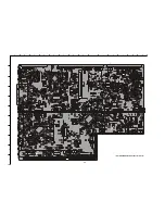
Page 30: ...A B C D E F G H I J K L M N 1 2 3 4 5 6 7 8 9 10 11 29 A PrintedWiring Board Conductor side A ...
Page 31: ...A B C D E F G H I J K L M N 1 2 3 4 5 6 7 8 9 10 11 30 A PrintedWiring Board Conductor side B ...
Page 36: ... 35 G Schematic Power Supply ...
Page 37: ... 36 D Schematic Deflection ...
Page 39: ...A B C D E F G H I J K L M N 1 2 3 4 5 6 7 8 9 10 11 38 C Board Schematic R G B Out ...
Page 41: ... 40 M Schematic Micro Processor ...
Page 70: ... 69 ...


