background image

Specifications


FCB-EH6500(GB)   A-EEP-100-11(1)

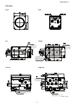
Dimensions

Unit: mm (inches)

Front

Back

Top

Bottom

Within a depth of 3 mm (

1

/

8

 in.) or 

less from the side

Within a depth of 3 mm (

1

/

8

 in.) or 

less from the side

Within a depth 

of 3 mm (

1

/

8

 in.) 

or less from the 

bottom surface

Within a depth 

of 3 mm (

1

/

8

 in.) 

or less from the 

top surface

Left side

Right side

Screw for camera 

tripod within a depth 

of 5 mm (

7

/

32

 in) or 

less (1/4-20UNC)

Within a depth of 

2.5 mm (

1

/

8

 in.) or 

less from the side

Summary of Contents for FCB-CV7320

Page 1: ... 2015 Sony Corporation Color Camera Module FCB EV7320 FCB CV7320 C 217 100 11 1 Technical Manual ...

Page 2: ...ols 6 Basic Functions 7 Overview of Functions 7 User s Updating 20 Eclipse 23 Spectral Sensitivity Characteristics 23 Initial Settings Custom Preset and Backup 24 Mode Condition 26 Command List 29 VISCA RS 232C Commands 29 FCB Camera Commands 35 Specifications 56 ...

Page 3: ...Full HD 60fps output image Low focal plane distortion image using the high speed readout of imager The following functions are provided Noise Reduction NR Tone correction Visibility Enhancer and Defog functions Lens The camera is equipped with a bright lens with 20 optical zoom and F1 6 aperture optical zoom digital zoom 240 With consideration given environmental protection this module is designed...

Page 4: ...f exposed to static electricity When directly handling this camera wear an antistatic strap spread a conductive sheet or similar item under your workbench and take measures to eliminate static electricity Precautions In case of abnormal operation contact your authorized Sony dealer or the store where you purchased the product Phenomena specific to CMOS image sensors The following phenomena that ma...

Page 5: ...ided with the distribution 3 Neither the name of the copyright holder nor the names of contributors may be used to endorse or promote products derived from this software without specific prior written permission THIS SOFTWARE IS PROVIDED BY THE AUTHOR AND CONTRIBUTOR S AS IS AND ANY EXPRESS OR IMPLIED WARRANTIES INCLUDING BUT NOT LIMITED TO THE IMPLIED WARRANTIES OF MERCHANTABILITY AND FITNESS FOR...

Page 6: ...tions of Controls Lens CN401 connector CN501 connector Tripod screw hole When a tripod is used please use 5 mm 7 32 in or less screw to attach it to the camera Also please be sure to attach the tripod securely Front Back Bottom ...

Page 7: ... Powers the camera on and off When the power is off the camera is able to accept the VISCA Commands although the screen is set non displayed I F Clear Clears the Command buffer of the FCB camera Address Set VISCA is a protocol which normally supports a daisy chain of up to seven connected cameras via RS 232C interface In such cases the address set command can be used to assign addresses from 1 to ...

Page 8: ...the following modes Auto Focus Mode The minimum focus distance is 10 mm at the optical wide end and 1000 mm at the optical tele end and is independent of the digital zoom The Auto Focus AF function automatically adjusts the focus position to maximise the high frequency content of the picture in a center measurement area taking into consideration the high luminance and strong contrast components No...

Page 9: ... High pressure sodium lamps are supported Proper white balance may not be captured for some subjects when using low pressure sodium lamps Auto Exposure Mode AE A variety of AE functions are available for optimal output of subjects in lighting conditions that range from low to high Full Auto Iris Gain and Shutter Speed can be set automatically Gain Limit Setting The gain limit can be set at the Ful...

Page 10: ...s to the screen can be minimized in that area As shown in the diagram below a range of 16 blocks vertically and 16 blocks horizontally can be designated In the case where the center is designated shown in black the level is computed along with a weighted value for the surrounding block shaded including the Data 60 59 94 30 29 97 mode 50 25 mode 15 1 10000 1 10000 14 1 6000 1 6000 13 1 4000 1 3500 ...

Page 11: ...adjusts the exposure so that it can shoot a high intensity subject in this case the headlights As a result images around the headlights that is the rest of the subject except the headlights becomes relatively dark and poorly distinguished However using the slow AE function means the AE response speed will be slower and response time will be longer As a result even if the camera catches a high inte...

Page 12: ...Angle of view and resolution Optical zoom Digital zoom StableZoom The digital zoom is not switched On at the wide end HLC HLC highlight correction is a function to adjust AE and AF and to perform the masking of light area as required when a high intensity spot light is detected It allows you to easily read the number of vehicles and number plate in the indoor parking area or in the outdoor during ...

Page 13: ...ight color is particularly important The initial setting 100 4h can be set to range from approx 60 0h to 200 Eh with 15 stages Custom Color Phase You can configure the color phase The initial setting 0 degrees 7h is adjustable between approx 14 degrees 0h to 14 degrees Eh in 15 increments Auto ICR Mode Auto ICR Mode automatically switches the settings needed for attaching or removing the IR Cut Fi...

Page 14: ...e Minimum Shutter Limit Custom Preset As with the position preset function the camera shooting conditions can be stored and recalled The settings are recalled when the power is turned on For setting items see the Initial Settings Custom Preset and Backup section on page 24 User Memory Area A user area of 16 bytes allows you to write data such as an ID for each customer data for each system and so ...

Page 15: ...ote After changing the register setting turn off the camera then turn it on again Privacy Zone Masking Settings For details see page 16 Motion detection For details see page 18 Title Display You can set a title of up to 11 lines One line can contain up to 20 characters You can set display on off the horizontal position of the first character blinking state and color for each line The camera gives ...

Page 16: ...isplay a Privacy zone you must set its bit to 1 If you do not want to display a Privacy zone you must set its bit to 0 Set Mask Color Command 8x 01 04 78 pp pp pp pp qq rr FF Parameter pp pp pp pp Each 24 Privacy Zones correspond to the BIT See pp pp pp pp Mask bit in Parameters on page 18 qq Set the color code rr Set the color code See qq rr Color code in Parameters on page 18 Comments Two differ...

Page 17: ...mal number Note Privacy mask zone follows the change of angle of view according to zoom However the follow might be delayed for a moment if there is any big change such as when using D Zoom or E FLIP Non Interlock Mask Command 8x 01 04 6F mm 0p 0p 0q 0q 0r 0r 0s 0s FF Parameters mm Setting Mask See mm Mask setting list in Parameters on page 17 pp Sets the center position x of the Mask on screen qq...

Page 18: ...n motion is detected within the range where frames overlap The alarms are sent for both frames At this position the alarm for frame 3 is sent Within this overlapped range alarms are sent for both frame 3 and frame 4 Frame 1 Frame 2 Frame 3 Frame 4 Note The priority order of the mask display is in the sequence from A highest to X lowest When you set the parameters of masks non sequentially it is re...

Page 19: ... motion is detected in the set frame the camera issues this command This command includes the information on the number of the detected frame y0 07 04 1B 0p FF p Frame Number bit0 Frame0 bit1 Frame1 bit2 Frame2 bit3 Frame3 Setting Commands MD On Off The Display mode is selected by the Function Set command and frames are set by the Frame Set command By sending an MD On command the frame is displaye...

Page 20: ... to the maintenance mode using the Visca command 2 Binary transmission X model protocol of the firmware in the maintenance mode 3 Finalizing setting using the Visca command Each step is described as follows 1 Shifting to the maintenance mode using the Visca command After entering the standby mode using the Visca command the unit shifts to the maintenance mode When shifting to the maintenance mode ...

Page 21: ...FF ACK COMP Enter Standby Mode Enter Maintenance Mode Writing of Writer program in FlashROM When power is off during this period camera will be broken REBOOT AUTOMATICALLY Maintenance Mode Sending firmware When power is off during this period camera will be broken Sending Firmware Binary with X modem protocol Firmware Update Ready Message HOST FCB reboot CR CODE NAME VERSION CR ready CR reprogram ...

Page 22: ...3 00 00 06 01 FF ACK COMP 8x 01 7F 7F 02 03 00 01 06 01 FF ACK COMP 8x 09 7F 7F 01 03 00 02 FF 8x 09 00 02 FF 9x 50 00 00 00 01 FF is received 1 8x 01 04 19 03 FF 9x 50 00 20 HH HH JJ JJ 02 FF is received Check that JJJJ is the same as the updated FW version 2 1 When 9x 50 00 00 00 00 FF is received retransmit 8x 09 7F 7F 01 03 00 02 FF until 9x 50 00 00 00 01 FF is received 2 If it is not the sam...

Page 23: ... 8 56 4 71 2 Spectral Sensitivity Characteristics 0 0 0 2 0 4 0 6 0 8 1 0 400 500 600 700 800 900 1000 Relative response a u Wavelength nm Red Green Blue Use the graph as a reference value We can not guarantee these values This data is measured when the IR cut filter is removed and the characteristics of the lens and optical source characteristics are ignored ...

Page 24: ...ckup Mode Position setting Initial Settings Custom Preset Back up at standby Zoom Position Wide end D Zoom On Off On D Zoom Separate Combine Combine D Zoom Position 00h Focus Position Focus Auto Manual Auto Near Limit Setting D000 30 cm AF Sensitivity Normal AF Mode Normal AF Run Time 5 sec AF Interval 5 sec WB Mode Auto WB Data Rgain Bgain One Push WB Data AE Mode Full Auto AE Response 01 Auto Sl...

Page 25: ...uminance Color Setting Cb 14h Low Illumination Chroma Suppress 2h Mid Color Gain 4h 100 Color Hue 7h 0 degrees Title Display On Off Off Title Setting Mask Setting Mask Display On Off Off Mask Color Setting Center Line Display On Off Off E Flip On Off Off Privacy Zone On Off Off Privacy Zone Setting Camera ID 0000h MD On Off Off MD Display Setting Off MD Threshold Level 10h MD Interval 1 sec MD Win...

Page 26: ...Zoom Direct Focus Direct ZmFo Direct Focus Auto Zoom Tele Wide Stop Zoom Direct Zoom Focus Direct D Zoom On Off D Zoom Separate Combine D Zoom Tele Wide Stop D Zoom 1 Max D Zoom Direct Focus Far Near Stop Focus Direct Focus Auto Manual One Push AF Focus Near Limit AF Sensitivity Normal Low AF Mode Norm Interval Zoom AF Activation Time Interval Setting Camera Memory Set Reset Camera Memory Recall L...

Page 27: ...Exposure Mode Power Off Initializing Power On Freeze On MemRecall AE Full Auto AE Manual Shutter Priority Iris Priority Bright Defog HLC AE Full Auto AE Manual Shutter Priority Iris Priority Bright Shutter Setting Iris Setting Gain Setting Bright Setting Auto Slow Shutter On Off Exposure Compensation On Off Exposure Compensation Setting BackLight On Off SpotAE On Off SpotAE Setting Defog On Off Mi...

Page 28: ...ze On Off Picture Effect Setting ICR On Off Auto ICR On Off Auto ICR Threshold Level Setting Auto ICR Alarm On Off Display On Off Mute On Off Title Setting Mask On Off Mask Setting MD On Off MD Function Setting MD Window Setting ID Write Memory Save Register Value Setting Color Enhancement On Off NR Level Setting Chroma Suppress Color Gain Color Hue ...

Page 29: ...HAT SOFTWARE DEVELOPED BASED ON THIS CONTROL PROTOCOL AND COMMAND LIST MAY CAUSE MALFUNCTION OR DAMAGE TO HARDWARE AND SOFTWARE USED WITH IT INCLUDING SONY HARDWARE AND SOFTWARE AND SPECIFICALLY DISCLAIMS ANY LIABILITY FOR ANY SUCH MALFUNCTION OR DAMAGE THIS CONTROL PROTOCOL AND COMMAND LIST SHOULD BE USED WITH CAUTION Overview of VISCA In VISCA the device outputting commands for example a compute...

Page 30: ...ess 2 is A0h Some of the commands for setting cameras can be sent to all devices at one time broadcast In the case of broadcast the header should be hexadecimal 88h When the terminator is FFh it signifies the end of the packet Command and inquiry Command Sends operational commands to the FCB camera Inquiry Used for inquiring about the current state of the FCB camera Command Packet Note Inquiry 8X ...

Page 31: ...ket to be cancelled X0 6Y 41 FF Command not executable X 9 to F FCB camera address 8 Y socket number Socket number When command messages are sent to the FCB camera send the next command message after waiting for the completion message or error message to return However to deal with advanced uses the FCB camera has two buffers memories for commands so that up to two commands including the commands ...

Page 32: ...rk Change X0 38 FF X 9 to F FCB camera address 8 VISCA interface command IF_Clear Clears the command buffers in the FCB camera and cancels the command currently being executed Command Packet Reply Packet Note IF_Clear 8X 01 00 01 FF X0 50 FF IF_Clear broadcast 88 01 00 01 FF 88 01 00 01 FF X 1 to 7 FCB camera board address For inquiry packet X 9 to F FCB camera board address 8 For reply packet VIS...

Page 33: ...Executable 90 62 41 FF Could not execute the command in the current mode Inquiry Command 81 09 04 38 FF Example 90 50 02 FF Completion Acknowledge is not returned for the inquiry command 81 09 05 38 FF Example 90 60 02 FF Syntax Error Accepted an incompatible command Address Set 88 30 01 FF 88 30 02 FF Returned the device address to 1 IF_Clear Broadcast 88 01 00 01 FF 88 01 00 01 FF Returned the s...

Page 34: ... two commands and the command could not be accepted when received Command Canceled z0 6y 04 FF y Socket No Returned when a command which is being executed in a socket specified by the cancel command is canceled The completion message for the command is not returned No Socket z0 6y 05 FF y Socket No Returned when no command is executed in a socket specified by the cancel command or when an invalid ...

Page 35: ...ring Separate Mode Direct 8x 01 04 46 00 00 0p 0q FF pq D Zoom Position Enabled during Separate Mode CAM_Focus Stop 8x 01 04 08 00 FF Far Standard 8x 01 04 08 02 FF Near Standard 8x 01 04 08 03 FF Far Variable 8x 01 04 08 2p FF p 0 Low to 7 High Near Variable 8x 01 04 08 3p FF Direct 8x 01 04 48 0p 0q 0r 0s FF pqrs Focus Position Auto Focus 8x 01 04 38 02 FF AF On Off Manual Focus 8x 01 04 38 03 F...

Page 36: ...02 FF Down 8x 01 04 04 03 FF Direct 8x 01 04 44 00 00 0p 0q FF pq B Gain CAM_AE Full Auto 8x 01 04 39 00 FF Auto Exposure mode Manual 8x 01 04 39 03 FF Manual Control mode Shutter Priority 8x 01 04 39 0A FF Shutter Priority Auto Exposure mode Iris Priority 8x 01 04 39 0B FF Iris Priority Auto Exposure mode Bright 8x 01 04 39 0D FF Bright Mode Manual control CAM_AutoSlowShutter On 8x 01 04 5A 02 FF...

Page 37: ...k 2 Standard 3 Bright s Compensation level 0 Low 1 Mid 2 High CAM_Defog On 8x 01 04 37 02 0p FF Defog On Off p Defog level 1 low 2 mid 3 high Off 8x 01 04 37 03 00 FF CAM_Aperture Reset 8x 01 04 02 00 FF Aperture Control Up 8x 01 04 02 02 FF Down 8x 01 04 02 03 FF Direct 8x 01 04 42 00 00 0p 0q FF pq Aperture Gain CAM_HR On 8x 01 04 52 02 FF High Resolusion Mode On Off Off 8x 01 04 52 03 FF CAM_NR...

Page 38: ...qq Blink Title Set2 8x 01 04 73 2L mm nn pp qq rr ss tt uu vv ww FF L Line Number mnpqrstuvw Setting of characters 1 to 10 Title Set3 8x 01 04 73 3L mm nn pp qq rr ss tt uu vv ww FF L Line Number mnpqrstuvw Setting of characters 11 to 20 Title Clear 8x 01 04 74 1p FF Title Setting clear p 0h to Ah F all lines On 8x 01 04 74 2p FF Title display On Off p 0h to Ah F all lines Off 8x 01 04 74 3p FF CA...

Page 39: ...2 FF Focus Position data Continuous Output On Off Off 8x 01 04 16 03 FF Reply y0 07 04 16 00 00 0p 0p 0p 0p FF pppp Focus Position CAM_FocusPosReply IntervalTimeSet 8x 01 04 1A 00 00 0p 0p FF pp Interval Time V cycle CAM_RegisterValue 8x 01 04 24 mm 0p 0p FF mm Register No 00h to 7Fh pp Register Value 00h to FFh CAM_ColorEnhance Parameter Set 8x 01 04 20 mm 00 pp qq rr ss tt uu FF mm Threshold lev...

Page 40: ...ever 00h is the same operation as 01h Down 8x 01 04 1F 02 03 pp FF Aperture control down pp Step number pp 00h to 7Fh However 00h is the same operation as 01h Direct 8x 01 04 1F 42 00 00 0p 0q FF Set the aperture control to the specified level pq Level pq 00h to FFh CAM_ExAutoICR Threshold ON OFF 8x 01 04 1F 21 00 00 0p 0q FF pq ICR On Off threshold level when Auto ICR pq 00h to FFh On Level 8x 01...

Page 41: ...CorrectionInq 8x 09 04 11 FF y0 50 00 FF Standard y0 50 01 FF IR Light CAM_WBModeInq 8x 09 04 35 FF y0 50 00 FF Auto y0 50 01 FF Indoor y0 50 02 FF Outdoor y0 50 03 FF One Push WB y0 50 04 FF ATW y0 50 05 FF Manual y0 50 06 FF Outdoor Auto y0 50 07 FF Sodium Lamp Auto y0 50 08 FF Sodium Lamp y0 50 09 FF Sodium Lamp Outdoor Auto CAM_RGainInq 8x 09 04 43 FF y0 50 00 00 0p 0q FF pq R Gain CAM_BGainIn...

Page 42: ...Noise Reduction p 00h to 05h CAM_GammaInq 8x 09 04 5B FF y0 50 0p FF Gamma p 00h 01h CAM_HighSensitivityInq 8x 09 04 5E FF y0 50 02 FF On y0 50 03 FF Off CAM_LR_ReverseModeInq 8x 09 04 61 FF y0 50 02 FF On y0 50 03 FF Off CAM_FreezeModeInq 8x 09 04 62 FF y0 50 02 FF On y0 50 03 FF Off CAM_PictureEffectModeInq 8x 09 04 63 FF y0 50 00 FF Off y0 50 02 FF Neg Art y0 50 04 FF Black White CAM_PictureFli...

Page 43: ...meInq 8x 09 04 1A FF y0 50 00 00 0p 0p FF pp Interval Time CAM_RegisterValueInq 8x 09 04 24 mm FF y0 50 0p 0p FF mm Register No 00h to 7Fh pp Register Value 00h to FFh CAM_ColorEnhanceInq 8x 09 04 20 FF y0 50 mm 00 pp qq rr ss tt uu FF mm Threshold level pp Y fixed color for high intensity qq Cr fixed color for high intensity rr Cb fixed color for high intensity ss Y fixed color for low intensity ...

Page 44: ...t Comments CAM_MinShutterInq 8x 09 04 12 FF y0 50 02 FF On y0 50 03 FF Off CAM_MinShutterLimitInq 8x 09 04 13 FF y0 50 00 00 0p 0q FF pq MinShutter Position CAM_HLCInq 8x 09 04 14 FF y0 50 0p 0q FF p HLC level 0 Off 1 Low 2 Mid 3 High q HLC mask level 0 Off 1 to F from low to high level ...

Page 45: ... 1 0 1 2 AF Sensitivity 0 Low 1 Normal 0 0 0 2 7 0 8 7 0 1 Digital Zoom 1 On 0 Off 6 0 6 0 0 Focus Mode 0 Manual 1 Auto 5 0 5 0 14 7 0 4 0 4 0 6 0 3 Zoom Position HH 3 Focus Position HH 5 0 2 2 4 0 1 1 3 Low Contrast Detection 1 Yes 0 No 0 0 3 7 0 9 7 0 2 Camera Memory Recall 1 Executing 0 Stopped 6 0 6 0 5 0 5 0 1 Focus Command 1 Executing 0 Stopped 4 0 4 0 3 Zoom Position HL 3 Focus Position HL ...

Page 46: ...ion 3 0 3 Aperture Gain 3 2 0 2 2 1 0 1 1 0 0 0 0 2 7 0 8 7 0 14 7 0 6 0 6 0 6 0 5 0 5 0 5 0 4 0 4 Exposure Mode 4 0 3 R Gain H 3 3 Exposure Comp Position 2 2 2 1 1 1 0 0 0 3 7 0 9 7 0 15 7 1 Terminator FFh 6 0 6 0 6 1 5 0 5 High Resolution 1 On 0 Off 5 1 4 0 4 VE 1 On 0 Off 4 1 3 R Gain L 3 Spot AE 1 On 0 Off 3 1 2 2 Backlight 1 On 0 Off 2 1 1 1 Exposure Comp 1 On 0 Off 1 1 0 0 Slow Shutter 1 On ...

Page 47: ... 0 6 0 3 0 3 0 5 0 2 0 2 0 4 0 1 0 1 0 3 0 0 0 0 0 2 0 2 7 0 8 7 0 1 0 6 0 6 0 0 0 5 0 5 0 14 7 0 4 0 4 0 6 0 3 Auto ICR Alarm 1 On 0 Off 3 Camera ID HH 5 0 2 Auto ICR 1 On 0 Off 2 4 0 1 0 1 3 0 0 Power 1 On 0 Off 0 2 0 3 7 0 9 7 0 1 0 6 0 6 0 0 0 5 0 5 0 15 7 1 Terminator FFh 4 ICR 1 On 0 Off 4 0 6 1 3 Freeze 1 On 0 Off 3 Camera ID HL 5 1 2 LR Reverse 1 On 0 Off 2 4 1 1 0 1 3 1 0 0 0 2 1 4 7 0 10...

Page 48: ... 12 7 0 5 0 5 0 6 0 4 1 4 0 5 0 3 0 3 AF Interval Time L 4 AE Response 2 0 2 3 1 0 1 2 0 0 0 1 2 7 0 8 7 0 0 6 0 6 0 13 7 0 5 0 5 0 6 Gamma 4 0 4 0 5 3 Digital Zoom Position H 3 Spot AE Position X 4 2 2 3 High Sensitivity mode 1 On 0 Off 1 1 0 0 2 NR Level 3 7 0 9 7 0 1 6 0 6 0 0 5 0 5 0 14 7 0 4 0 4 0 6 Chroma Suppress 3 Digital Zoom Position L 3 Spot AE Position Y 5 2 2 4 1 1 3 Gain Limit 0 0 2 ...

Page 49: ...0 3 0 3 0 2 0 2 0 2 0 1 0 1 0 1 0 0 0 0 Defog 0 Off 1 On 0 0 2 7 0 8 7 0 13 7 0 6 0 6 0 6 0 5 0 5 0 5 0 4 0 4 0 4 0 3 0 3 0 3 0 2 0 2 0 2 0 1 VE 0 Off 2 VE On 1 Defog Level 1 low 2 mid 3 high 1 0 0 0 0 0 3 7 0 9 7 0 14 7 0 6 0 6 0 6 0 5 0 5 0 5 0 4 0 4 0 4 0 3 0 3 0 3 0 2 0 2 0 2 0 1 0 1 0 1 0 0 0 0 0 0 0 4 7 0 10 7 0 15 7 1 Terminator FFh 6 0 6 0 6 1 5 0 5 0 5 1 4 0 4 0 4 1 3 0 3 0 3 1 2 Display ...

Page 50: ...pletion Message 50h 7 7 0 12 7 0 6 1 6 Reserved 6 Reserved 5 0 5 5 4 1 4 4 3 0 3 3 2 0 2 2 1 0 1 1 0 0 0 0 2 7 0 8 7 0 13 7 0 6 0 6 Reserved 6 Reserved 5 0 5 5 4 0 4 4 3 Color Hue 0h 14 degrees to Eh 14 degrees 3 3 2 2 2 1 1 1 0 0 0 3 7 0 9 7 0 14 7 0 6 Reserved 6 Reserved 6 Reserved 5 5 5 4 4 4 3 3 3 2 2 2 1 1 1 0 0 0 4 7 0 10 7 0 15 7 1 Terminator FFh 6 Reserved 6 Reserved 6 1 5 5 5 1 4 4 4 1 3 ...

Page 51: ...1 1 1 Iris 11 F1 6 10 F2 0F F2 4 0E F2 8 0D F3 4 0C F4 0B F4 8 0A F5 6 09 F6 8 08 F8 07 F9 6 06 F11 05 F14 00 CLOSE Gain 0F 50 5 dB 28 step 0E 46 9 dB 26 step 0D 43 3 dB 24 step 0C 39 7 dB 22 step 0B 36 1 dB 20 step 0A 32 5 dB 18 step 09 28 8 dB 16 step 08 25 2 dB 14 step 07 21 6 dB 12 step 06 18 0 dB 10 step 05 14 4 dB 8 step 04 10 8 dB 6 step 03 7 2 dB 4 step 02 3 6 dB 2 step 01 0 dB 0 step Gain...

Page 52: ...tep 0E F2 8 0 dB 0 step 0D F3 4 0 dB 0 step 0C F4 0 dB 0 step 0B F4 8 0 dB 0 step 0A F5 6 0 dB 0 step 09 F6 8 0 dB 0 step 08 F8 0 dB 0 step 07 F9 6 0 dB 0 step 06 F11 0 dB 0 step 05 F14 0 dB 0 step 00 CLOSE 0 dB 0 step Exposure Comp 0E 7 10 5 dB 0D 6 9 dB 0C 5 7 5 dB 0B 4 6 dB 0A 3 4 5 dB 09 2 3 dB 08 1 1 5 dB 07 0 0 dB 06 1 1 5 dB 05 2 3 dB 04 3 4 5 dB 03 4 6 dB 02 5 7 5 dB 01 6 9 dB 00 7 10 5 dB...

Page 53: ... m 9000 1 85 m A000 1 5 m B000 1 23 m C000 1 m D000 30 cm initial setting E000 8 cm F000 1 cm As the distance on the left will differ due to temperature characteristics etc use as approximate values The lower 1 byte is fixed at 00 Wide Tele Limit Setting Wide Tele Limit Setting Value Wide Limit Tele Limit Limit Setting Value Zoom Position Zoom Ratio Zoom Position Zoom Ratio 00 0000 1 4000 20 0 10 ...

Page 54: ...7 07 1080p 30 08 1080p 25 09 720p 59 94 0A 720p 60 0B Reserved 0C 720p 50 0D Reserved 0E 720p 29 97 0F 720p 30 10 Reserved 11 720p 25 12 Reserved 13 1080p 59 94 14 1080p 50 15 1080p 60 LVDS Mode 74 00 Iinitial Setting Single Output 01 Double Output Zoom Limit 50 00 FF Iinitial Setting 00 Wide Limit 0 Disabled 51 00 FF Iinitial Setting 00 Tele Limit 0 Disabled D Zoom Max 52 00 EB Iinitial Setting E...

Page 55: ...Off bit 1 Aperture Extended 256 levels On Off bit 2 Color Gain Hue Extended 256 levels On Off bit 3 Auto ICR Off On setting enable On Off For all of bit 1 is to activate 0 is Off Others AF Active Time1 00 to FF AF Interval Time1 00 to FF Spot AE X position 00 to 0F Spot AE Y position 00 to 0F R Gain 00 to FF B Gain 00 to FF Aperture Control Level 00 to 0F AE Response 01 to 30 AutoICR On Off Thresh...

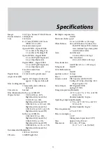
Page 56: ... 30 sec 50 High Sensitivity mode On 0 006 lx 1 30 sec 50 High Sensitivity mode Off 0 0008 lx 1 4 sec 1 3 sec 30 High Sensitivity mode On Recommended illumination 100 lx to 100 000 lx S N ratio 50 dB Weight On Back light compensation On Off Electronic shutter speed 1 1 sec to 1 10000 sec 22 steps White Balance Auto ATW Indoor Outdoor One Push WB Manual WB Outdoor Auto Sodium Vapor Lamp Fix Auto Out...

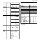
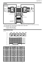
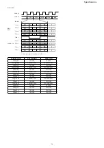
Page 57: ...4 Y3 Y2 Y1 Y0 0 0 Y7 C6 C5 C4 C3 C2 C1 C0 0 0 0 0 0 C6 C7 TA1 TB1 TC1 TD1 TCLK Please ignore the value which can be 0 or 1 FCB OUT Single Mode 0 Output Format Pixel CLK Hz TCLK Hz 1080p 60 148 5M 148 5M 1080p 59 94 148 5M 1 001 148 5M 1 001 1080p 30 74 25M 74 25M 1080p 29 97 74 25M 1 001 74 25M 1 001 1080i 60 74 25M 74 25M 1080i 59 94 74 25M 1 001 74 25M 1 001 1080i 50 74 25M 74 25M 720p 60 74 25M...

Page 58: ... ignore the value which can be 0 or 1 0 0 Output Format Pixel CLK Hz TCLK Hz 1080p 60 148 5M 74 25M 1080p 59 94 148 5M 1 001 74 25M 1 001 1080p 30 74 25M 37 125M 1080p 29 97 74 25M 1 001 37 125M 1 001 1080i 60 74 25M 37 125M 1080i 59 94 74 25M 1 001 37 125M 1 001 1080i 50 74 25M 37 125M 720p 60 74 25M 37 125M 720p 59 94 74 25M 1 001 37 125M 1 001 720p 30 74 25M 37 125M 720p 29 97 74 25M 1 001 37 1...

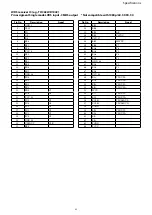
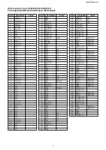
Page 59: ... 21 TXOUT0 22 TXOUT0 23 TXOUT1 24 TXOUT1 25 TXOUT2 26 TXOUT2 27 TXCLKOUT 28 TXCLKOUT 29 TXOUT3 30 TXOUT3 C1 FB002 C005 1u 25V C007 0 1u 25V R001 100 Y2 Y3 R027 10k Y6 C7 IC001 THC63LVD104C 1 GND_1 2 TEST 3 PD 4 OE 5 R F 6 RE6 7 RE5 8 RE4 9 VCC_9 10 RE3 11 RE2 12 RE1 13 RE0 14 RD6 15 RD5 16 GND_16 RD4 17 RD3 18 RD2 19 RD1 20 RD0 21 RC6 22 VCC_23 23 RC5 24 RC4 25 RC3 26 RC2 27 RC1 28 RC0 29 GND_30 3...

Page 60: ...CLK TXCLKOUT 57 RCLK TXCLKOUT 58 LGND 59 RD TXOUT3 60 RD TXOUT3 61 RE 62 RE 63 PGND 64 PVCC Pin No Description Signal 1 GND_1 2 TEST 3 PD 4 OE 5 R F 6 RE6 7 RE5 8 RE4 9 VCC_9 10 RE3 11 RE2 12 RE1 13 RE0 14 RD6 15 RD5 16 GND_16 17 RD4 18 RD3 19 RD2 20 RD1 21 RD0 C7 22 RC6 C6 23 VCC_23 24 RC5 C5 25 RC4 C4 26 RC3 C3 27 RC2 C2 28 RC1 C1 29 RC0 C0 30 GND_30 31 CLKOUT CLK 32 RB6 LVDS receiver IC e g THC...

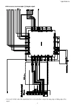
Page 61: ...Specifications 61 LVDS receiver circuit example Single output No 1 and 2 of S601 adjust the signal delay No 3 selects whether to input the rising edge or falling edge of the signal ...

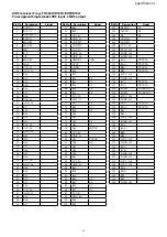
Page 62: ...60 CLKOUT CLK 61 CVCC 62 CGND 63 R10 64 R11 65 R12 Y0 66 R13 Y1 67 R14 Y2 68 R15 Y3 69 R16 Y4 70 VCC_70 71 GND_71 72 R17 Y5 73 R18 C7 74 R19 C6 75 G10 76 G11 77 G12 Y6 78 G13 Y7 79 G14 HSYNC 80 VCC_80 81 GND_81 82 G15 VSYNC 83 G16 DE 84 G17 85 G18 86 G19 87 B10 88 VCC_88 89 GND_89 90 B11 91 B12 92 B13 93 B14 C0 94 B15 C1 95 B16 C2 96 B17 C3 97 VCC_97 98 GND_98 99 B18 100 B19 Pin No Description Sig...

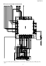
Page 63: ...Specifications 63 LVDS receiver circuit example Double output No 1 and 2 of S601 adjust the signal delay No 3 selects whether to input the rising edge or falling edge of the signal ...

Page 64: ...6 78 G13 Y7 79 G14 HSYNC 80 VCC_80 81 GND_81 82 G15 VSYNC 83 G16 84 G17 85 G18 86 G19 87 B10 88 VCC_88 89 GND_89 90 B11 91 B12 92 B13 93 B14 C0 94 B15 C1 95 B16 C2 96 B17 C3 97 VCC_97 98 GND_98 99 B18 100 B19 LVDS receiver IC e g THC63LVD1024 BU90R102 Pin assigment Double mode LVDS input CMOS output Pin No Description Signal 101 HSYNC C4 102 VSYNC C5 103 DE DE 104 CONT11 105 CONT12 106 VCC_106 107...

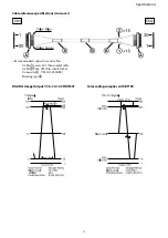
Page 65: ...put Y Cb Cr 4 2 2 FORMAT Color coding complies with BT709 Cable reference specifications crossover Recommended connectors and cables Cable green 42 thin coaxial cable Cable blue 42 thin coaxial cable Connector USL20 30S KEL Binding tape ...

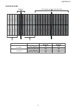
Page 66: ...0 0 X X Y Y Y Y Y Y Y Y Y P r P b P r P b P r P b P r P b P r P b P r P b F F Active Video Area or Non active Video Area EAV SAV Blanking XX for SAV XX for EAV First Field Active Video Area 80h 9Dh Non active Video Area ABh B6h Second Field Active Video Area C7h DAh Non active Video Area ECh F1h ...

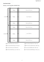
Page 67: ... Second Field Non active Video Area EAV for Second Field Active Video Area EAV for Second Field Non active Video Area Non active Video Area Active Video Area Non active Video Area Non active Video Area Active Video Area Non active Video Area Blanking Blanking Blanking Blanking Blanking First Field Second Field Blanking EAV for First Field Active Video Area EAV for First Field Non active Video Area...

Page 68: ...e system Comparable to SMPTE 274 M 296 M Non active Video Area Active Video Area Non active Video Area Blanking Blanking Blanking SAV EAV SAV for Active Video Area SAV for Non active Video Area EAV for Active Video Area EAV for Non active Video Area ...

Page 69: ...Within a depth of 3 mm 1 8 in or less from the side Within a depth of 3 mm 1 8 in or less from the bottom surface Within a depth of 3 mm 1 8 in or less from the top surface Left side Right side Screw for camera tripod within a depth of 5 mm 7 32 in or less 1 4 20UNC Within a depth of 2 5 mm 1 8 in or less from the side ...

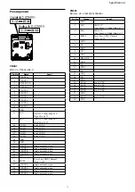
Page 70: ... out mode open 23 TXOUT6 Single out mode open 24 TXOUT6 Single out mode open 25 NC 26 RESET Reset Low GND Normal Open 1 8V 27 TXOUT5 Single out mode open 28 TXOUT5 Single out mode open 29 TXOUT4 Single out mode open 30 TXOUT4 Single out mode open CN501 Kyocera elco 046240024006800 Pin No Name Level 1 GND 2 TxD CMOS 5 V Low Max 0 1 V High Min 4 4 V 3 RxD CMOS 5 V Low Max 1 0 V High Min 2 3 V 4 RESE...

Reviews: