background image

74

Menu List


Cha

p

te

r 4  

 Men

u

 Con

fig

ur

at

ion an

d D

e

ta

iled

 S

e

tt

in

gs

<PB MIX 
SETTING>

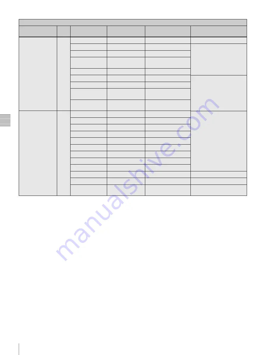
Setting for mixing 
the playback picture

09

(U08)

MIX TYPE

MIX

MIX, WIPE

MIX

DIRECTION

CAM

CAM, PB

MODE

Y-MIX

Y-MIX, WIRE(W), 
WIRE(B)

LEVEL

80%

0 to 80%

WIPE

LAYOUT

HOR

HOR, VERT

PB POSITION

HOR: RIGHT
VERT: BOTTOM

HOR: RIGHT, LEFT
VERT: BOTTOM, TOP

BOUNDARY

HOR: 960
VERT: 540

HOR: 0 to 1920
VERT: 0 to 1080

<SHUTTER 
ASSIGN>

Setting the step 
shutter values

10

(U10)

STEP

[deg] column: Shutter angle 

value settings

[sec] column: The converted 

speed values depending 
on the selected FPS value 
are displayed.

1

216.0

360.0 to 4.3

2

180.0

360.0 to 4.3

3

172.8

360.0 to 4.3

4

150.0

360.0 to 4.3

5

144.0

360.0 to 4.3

6

90.0

360.0 to 4.3

7

45.0

360.0 to 4.3

8

22.5

360.0 to 4.3

ADD

Execute by ENTER.

To add a step shutter value

DEL

Execute by ENTER.

To delete a step shutter value

PRESET

Execute by ENTER.

To resume the factory- set 
step shutter settings

OPERATION menu

Page title & 
purpose

No.

Item

Default

Settings

Remarks

Summary of Contents for F35 Cinealta

Page 1: ...OPERATION MANUAL English 1st Edition Revised 6 DIGITAL CINEMATOGRAPHY CAMERA F35 ...

Page 2: ...ables used to connect peripherals must be shielded in order to comply with the limits for a digital device pursuant to Subpart B of Part 15 of FCC Rules For the customers in Europe This product with the CE marking complies with the EMC Directive issued by the Commission of the European Community Compliance with this directive implies conformity to the following European standards EN55103 1 Electro...

Page 3: ... le service ou lagarantie veuillez consulter les adresses indiquées dans les documents de service ou de garantie séparés Um die Gefahr von Bränden oder elektrischen Schlägen zu verringern darf dieses Gerät nicht Regen oder Feuchtigkeit ausgesetzt werden Um einen elektrischen Schlag zu vermeiden darf das Gehäuse nicht geöffnet werden Überlassen Sie Wartungsarbeiten stets nur qualifiziertem Fachpers...

Page 4: ...corder 23 2 3 Mounting the CA F101 and Optical Connection 24 2 4 Attaching a Lens 25 2 5 Attaching a Viewfinder 26 2 6 Mounting the Camera to a Tripod 27 2 7 Attaching Detaching Handles 28 2 7 1 L Handle 28 2 7 2 Center Handle Supplied 28 2 8 Preparing the Power Supply 29 2 9 Setting the Built in Clock 31 Chapter 3 Basic Adjustments and Settings 3 1 Selection of the Basic Operation Modes 32 3 1 1 ...

Page 5: ...ing a Video Output Signal for Each Connector 46 3 5 2 Setting the Monitor Picture 47 3 5 3 Outputting Color Bars 49 3 6 Viewing and Setting the Viewfinder Displays 50 3 6 1 Viewing the Basic Status Indications 50 3 6 2 Viewing the LENS Lens Information Display 52 3 6 3 Viewing the ABNORMAL Display 52 3 6 4 Viewing the FUNCTION Format Switch Function Display 53 3 6 5 Setting the Marker Indications ...

Page 6: ...104 5 2 List of Items Stored in Files 106 5 3 File Operations 107 5 3 1 Using a Memory Stick 107 5 3 2 Storage and Retrieval of the Operator File 108 5 3 3 Registration and Retrieval of the Lens Files 109 5 3 4 Storage and Retrieval of the Scene Files 109 5 3 5 Storage and Retrieval of the Reference File 110 5 3 6 Reading of the User Gamma 111 5 3 7 Reading of the User MLUT 111 5 3 8 Storage of th...

Page 7: ...4 About a Memory Stick 135 Specifications 137 Camera Head 137 Interface Box Supplied 138 Optional Accessories 138 Connector Pin Assignments 140 Color Space According to the COLOR SPACE Settings 143 Lip Sync Compensation 144 High Sensitivity Shooting 145 Index 146 ...

Page 8: ...ting recording is selectable in single frame increments This allows users to create slow or fast motion effects equivalent to those obtained by overcranking or undercranking a cinematic film camera Frame rate settings for this function are variable from 1 to 50 FPS Multiple frame formats The camera covers the1080 formats of different types to allow it to be used for high end content creation inclu...

Page 9: ... adjusted in post production and Custom Mode which is suitable for users who wish to fine tune camera parameters to produce their desired look in on set grading Shutter control When using the electronic shutter the setting indication can be switched between the shutter angle degree and shutter speed second Monitor output selection For monitor outputs the user can select flexibly whether to mix cha...

Page 10: ...ata System and Cooke2 i Intelligent Electronic Lens System When a lens with corresponding characteristics is mounted information regarding the lens such as the type serial number iris setting and focus position may be available for on screen displays and metadata recording 1 ARRI Group 2 Cooke Optics Limited ...

Page 11: ...le Digital Recorder CA F101 Optical Fiber Camera Adapter Remote control devices System operating device Data storage media RM B750 Remote Control Unit MSU 1000 1500 Master Setup Unit MSU 900 950 Master Setup Unit HDFA 200 HD Optical FIber Adaptor Unit Memory Stick PRO Memory Stick PRO Duo Products for tripod mounting Name Model name Bridge Plate BP 5 ARRIFLEX made Shoulder Set S 1 ARRIFLEX made F3...

Page 12: ... between the camera and the SRW 1 HD Portable Digital Recorder SRPC 1 HD Video Processor with the HKSR 101 Optical Interface Unit via a hybrid optical camera cable For this system independent power supply to both the camera and the recorder is required Attaching the CA F101 to the top and the interface unit to the rear is also allowed For details refer to the Operation Manual of the CA F101 HDVF C...

Page 13: ...ACKER RET CTRL DC OUT 0 5A max DC OUT 4A max CAM SUB R DC OUT CAM MAIN L DC OUT DC IN AUDIO IN 2 AUDIO IN 1 PROMPTER1 GENLOCK IN CAM MAIN L REMOTE CAM SUB R REMOTE REMOTE VF REF OUT SDI IN MIC MIC LINE OFF 48V AES EBU LINE OFF 48V 60 5 6 8 11 16 CL 2 8 2 1 6 T ff 4 30 20 15 12 10 8 7 6 5 6 5 4 6 SDI IN CAM SUB R DC OUT REF OUT SDI IN REMOTE CAM MAIN L INTERCOM VF SDI2 OUT HDVF C950W C730W C550W EL...

Page 14: ... to the LENS connector f Viewfinder shoe Attach an optional viewfinder The height of the attaching position can be adjusted For details see 2 5 Attaching a Viewfinder page 26 g Flange focal length adjustment screw You can adjust the flange focal length with the screw behind the cover For details see Adjusting the flange focal length page 25 h Lens fixing lever Turn the lever clockwise to secure th...

Page 15: ...ither of the indicators lights according to the voltage of the power being supplied f CAM POWER switch CA The camera is turned on using the power being supplied via the interface box page 19 or CA F101 page 24 mounted on the rear Note that power is not supplied to an SRW 1 simultaneously mounted on the top via the interface box mounted on the rear To supply power to the SRW 1 use power supply via ...

Page 16: ... Right panel a Assignable buttons 1 2 3 You can assign various functions to these buttons using the subdisplay on the left panel or on the assistant panel or the menu displayed on the viewfinder or monitor screen No function is assigned at the factory For details see 3 2 11 Allocation of Functions to the Assignable Buttons and Switch page 41 and 3 7 Detailed Settings of the Switch Functions page 5...

Page 17: ...e camera For details see 5 3 1 Using a Memory Stick page 107 j Focus reference mark Used as a reference for focusing k Tripod receptacles bottom Two screw holes for 3 8 camera screws for tripod mounting are provided Display menu operation block Used to operate displays on the subdisplay and the viewfinder monitor screen For details on menu operations see 3 2 1 Basic Operation of the Subdisplay pag...

Page 18: ...o ON the indicator will be lit while the recorder mounted on the camera is in Recording mode g GENLOCK IN external sync signal input connector BNC type Used for input of an external gen lock signal HD 3 level sync h TEST OUT connector BNC type An analog test signal is fed from the connector The type of output signal can be set using a menu on the viewfinder or monitor screen i MONITOR OUT HD SDI c...

Page 19: ...onnectors XLR 3 pin female Connect audio signals Each connector is equipped with an input selection switch b Audio input selection switches Set to the appropriate position according to the equipment connected to the corresponding AUDIO IN connector LINE When a line level 4 dBu signal source is connected MIC When an external microphone is connected No power is supplied 48 V ON To supply power of 48...

Page 20: ...1 When the interface box is mounted on the top or rear of the camera head video audio and control signals are sent received to from the camera head f Camera connector 2 When the interface box is mounted on rear of the camera head power is sent received to from the camera head ...

Page 21: ...he interface box can be mounted unmounted with the L handle attached To attach 1 Place the camera head on a stable flat surface 2 Rotate the accessory clamp lever upward toward the lens when attaching to the top 3 Release the lock by sliding the lock release knob in the direction of the arrow 1 in the figure below then pull up the accessory mount lever pull it toward the lens when mounting on the ...

Page 22: ...n the figure below 2 Release the lock by sliding the lock release knob in the direction of the arrow 2 in the figure below then pull up on the accessory mount lever 3 in the figure below pull it toward the lens when mounting on the top 3 While holding the safety release tab pressed inward pull up on the interface box to disengage the connectors then pull out the box horizontally When attaching to ...

Page 23: ...amera to a Tripod page 27 When the camera is to be used with the recorder mounted make sure that the camera is securely fixed and stable so that it will not topple over or fall Mounting to the top Mounting to the rear When connecting the SRW 1 recorder using cables Attach the SRPC 1 HD Video Processor to the recorder to permit cable connection to the interface box mounted on the camera Use two coa...

Page 24: ...ing of the CA F101 refer to the Operation Manual of the CA F101 If the CA F101 is attached to the top of the camera the viewfinder can be placed to a higher position by attaching the viewfinder shoe supplied with the CA F101 to the adapter In this case remove the camera s viewfinder shoe to eliminate possible interference For details on viewfinder attachment see 2 5 Attaching a Viewfinder page 26 ...

Page 25: ...electing a lens file With this camera values such as the compensation values which are specific to the mounted lens can be registered in a lens file You can perform necessary adjustments upon replacement of lenses by merely invoking the registered file Select the file using the subdisplay For lens file selection on the subdisplay see 3 2 7 Selection of a Lens File page 40 For details on the lens f...

Page 26: ...the viewfinder and cause fire For details on the viewfinder refer to the instruction manual of the viewfinder If the viewfinder must be attached lower Loosen the two screws using the 2 5 mm wrench stored in the wrench box page 18 to detach the viewfinder shoe and attach it to the lower position using the lower screw holes Attaching procedure 1 Fit the viewfinder to the viewfinder shoe and slide th...

Page 27: ...e VF1 connector When two viewfinders are connected at the same time via the VF1 and VF2 connectors the HDVF C950W cannot be used because of a limitation of current capacity To detach the viewfinder Loosen the viewfinder positioning ring pull on the viewfinder stopper then pull out the viewfinder by sliding it in the direction opposite that when attaching 2 6 Mounting the Camera to a Tripod Two tri...

Page 28: ... 18 To attach the handle in the original position reverse the procedure for detaching 2 7 2 Center Handle Supplied The supplied center handle can be attached to the top or rear of the camera head Attach it so that the slanting side faces the back or bottom The screw holes on the upper side of the handle can be used for fixing various accessories Attaching the handle directly to the camera head The...

Page 29: ...nd the camera is turned on Power is also supplied to viewfinders connected to the VF1 or VF2 connector and a device connected to the LENS connector of the camera head Power of 12 V or 24 V can be fed to accessories via the DC OUT connectors Supplying power via the interface box or CA F101 To supply power via the interface box supplied or a CA F101 Optical Fiber Camera Adapter optional mount the in...

Page 30: ...a will be out of use for an extended period Charge the battery using the specified battery charger before use For charging refer to the instructions for the battery charger 1 Attach the BKP L551 Battery Adaptor to the interface box or the CA F101 2 Aligning the groove on the BP GL95 with the projection on the BKP L551 slide the BP GL95 so that the connectors engage 3 Connect the DC cable of the BK...

Page 31: ...d The following display examples are those in Custom mode They include some items not displayed in Cine EI mode and Cine mode 5 Turn the MENU SEL ENTER dial to scroll the page and position the pointer to DATE 6 Push on the MENU SEL ENTER dial The DATE page is displayed 7 Turn the MENU SEL ENTER dial and set the date and time Push on the MENU SEL ENTER dial to shift to the next digit 8 When the dat...

Page 32: ...lack balance ABB can be activated as auto setup The white balance level is fixed at the preset value 3200K and auto white balance AWB and WHITE R G B settings are not operative On a remote control unit connected to the REMOTE connector of the camera the values for the adjustment items whose settings fixed in Cine EI mode are not displayed However data for the ON OFF setting items and selectable it...

Page 33: ...d with wider color space than with the conventional cameras HDC F950 HDW F900R etc whose color space is equivalent to that available with film cameras With postproduction processes color expression can be substantially extended For details on reproducible gamuts see Color Space According to the COLOR SPACE Settings page 143 Images shot with the S GAMUT setting will be seen in somewhat pale colors ...

Page 34: ...ore than 1 second Data Change mode is entered the cursor starts flashing and the question mark symbol appears at the rightmost position on the first line On a page with two or more setting items each time the SET button is pressed the cursor moves to the next item Move the cursor to the item you wish to modify then change the setting by turning the MENU SEL ENTER dial While the subdisplay is in Da...

Page 35: ... Step mode is enabled with SHUTTER and adjustment in Continuous mode is enabled with ECS there is no need to set to ECS ON However to display the shutter values on the remote control unit correctly upgrading of the version is required For details consult your local Sony representative Shutter setting page To select a shutter value step by step In Step mode one of the registered shutter values 8 va...

Page 36: ...n the viewfinder For details on how to operate the menu see 4 2 Basic Menu Operations page 66 SHUTTER ASSIGN page STEP 1 8 In the deg column on each line the registered shutter angle is indicated In the sec column the shutter speed value converted according to the currently selected frame rate is displayed ADD For newly registering a step shutter value Display a shutter angle you wish to register ...

Page 37: ...to start the RAMP operation The FPS transition is executed in the duration you specified in step 3 The FPS value at 1 changes according to the transition progress and an asterisk appears at the right When the RAMP operation is completed the asterisk disappears and the starting FPS value 2 and ending FPS value 3 will be reversed You cannot change the 2 to 6 settings after starting the RAMP operatio...

Page 38: ...u wish to change and push on the MENU SEL ENTER dial The FORMAT MEMORY subpage for format selection will be displayed FORMAT MEMORY page Position the pointer to the format you wish to select and push on the MENU SEL ENTER dial The registered format will be changed If NO ASSIGN is selected selection with that number becomes invalid 3 2 5 Retrieving the ND Offset If an ND filter is attached to the m...

Page 39: ...nce Adjustment in Custom mode page 45 Indications of the ISO sensitivity and dynamic range The ISO sensitivity value displayed on the Gain setting page is defined as the value with which the video input becomes 20 when shooting a gray scale chart of 18 reflection rate Note that the video output value with respect to this input will vary depending on the selected gamma Either dynamic range or latit...

Page 40: ...ng Data 3 2 8 Confirmation of the Time Code and Tape Remaining When the SRW 1 HD Portable Digital Recorder is attached to this camera the time code of the recorder and approximate tape remaining unit minutes can be confirmed on the subdisplay Time code tape remaining display page The time code is displayed on the first line and the approximate tape remaining is displayed on the second line in the ...

Page 41: ...ANCE menu page 91 3 2 10 ON OFF of the Character Indication Superimposition of character data onto camera images can be activated or deactivated by output destination Character indication setting page VF1 Viewfinder connected via the VF1 connector default ON VF2 Viewfinder connected via the VF2 connector default ON MON Monitors connected via the MONITOR OUT HD SDI connectors default ON VBS Monitor...

Page 42: ... reproducibility can be selected on the color space selection page of the subdisplay The page is for display only and not operative in Cine EI mode Color space selection page Select the color space mode S GAMUT F900 F900R or DCDM REF PJ on the second line For information on color space modes see 3 1 2 Switching of the Basic Operation Modes page 33 and Color Space According to the COLOR SPACE Setti...

Page 43: ...ges ON OFF using the PAGE SELECT subpage that can be accessed from the SUBDISPLAY 2 page of the USER OPERATION menu For details on how to operate the menu see 4 2 Basic Menu Operations page 66 SUBDISPLAY 2 page Move the pointer to PAGE SELECT then push on the MENU SEL ENTER dial to jump to the PAGE SELECT subpage where limitation of display pages can be assigned PAGE SELECT page To switch ON OFF m...

Page 44: ...ingle execution of ABB adjustment To compensate for all three channels R G and B hold the 4 AUTO BLK BAL switch pressed to the AUTO BLK BAL position for more than 5 seconds After a single execution of ABB adjustment the white fleck automatic compensation is performed for G R then B in sequence The three channels are processed in a circumstantially determined order The order and the compensation da...

Page 45: ...t the lens iris opening or set the shutter to ON With a manually adjusted lens Set the opening to an appropriate value With a lens that has automatic iris control Set the lens automatic manual iris control switch to automatic Or set the video level to an appropriate value using the shutter setting 5 Perform automatic white balance adjustment To perform adjustment on the AUTO SETUP page of the MAIN...

Page 46: ...o 13 FPS or greater before the automatic white balance adjustment is to be performed Although the maximum FPS value is 50 FPS with S59 94PsF set it to 31 FPS or greater 3 5 Setting the Camera Outputs 3 5 1 Selecting a Video Output Signal for Each Connector The type of video signals to be output to the MONITOR OUT HD SDI 1 2 TEST OUT and REMOTE connectors can be selected For selection use the MONIT...

Page 47: ...e MONITOR OUTPUT page Selecting PBMIX permits you to compare the playback picture and the camera image by displaying them on the same screen How this is to be displayed can be set on the PB MIX SETTING page of the USER OPERATION menu see page 49 MLUT cannot be selected on the MLUT PBMIX line if no MLUT is selected in advance on the MLUT SEL line To apply monitor LUT to the monitor picture When SPE...

Page 48: ...t the camera to display the MLUT mark LUT to indicate that gamma that is different from that used for recording is applied The mark is not recorded with the docked recorder Set MLUT MARK to ON then set the brightness and position of the indication To monitor the playback picture The playback picture of the recorder can be confirmed with a monitor connected to the camera or on the viewfinder screen...

Page 49: ...ed Default WIPE The screen is horizontally or vertically split in two and two pictures are displayed simultaneously Item Setting Content DIRECTION CAM The playback picture is gradually mixed into the camera image Default PB The camera image is gradually mixed into the playback picture MODE Y MIX The Y signals are mixed Default WIRE W Only the outline components are mixed and displayed with white l...

Page 50: ... when you press the VF MENU DISPLAY button The display conditions can be specified on the VF DISPLAY page of the USER OPERATION menu a Frame rate The current frame rate is displayed b Battery indications The conditions of output power are indicated The left column is for DC 12V OUT power and the right column is for DC 24 V OUT power Each indication begins to flash if the corresponding input voltag...

Page 51: ...shutter angle is displayed at the left The type of the display angle deg or speed sec can also be switched on the VF DISPLAY page of the USER OPERATION menu default deg j Tape remaining The remaining time of the tape of the recorder docked on the camera is roughly indicated in minutes k Recording mode REC is displayed when the recorder docked on the camera is in REC mode l Iris setting Indicates t...

Page 52: ...lay is turned on or off in the IND column Set the normal condition for each item in the NORMAL column If an item for which IND is set to ON becomes a condition other than that specified in the NORMAL column the condition is indicated on the IND page IRIS Set to ON to obtain the iris setting indication qs ZOOM Set to ON to obtain the zoom position indication 4 ND Set to ON to obtain the optical fil...

Page 53: ... markers such as the center marker and safety zone marker can be displayed on the viewfinder and monitor screens Example Center marker entire cross Example Safety zone marker 90 The CHAR MARK MIX page and MARKER SETTING page of the USER OPERATION menu allow you to switch the display of the markers on or off and to set the display conditions of the markers Activating deactivating all the marker ind...

Page 54: ...Item Setting CENTER Set to ON to display the center marker and select the type of the center marker 1 Entire cross 2 Entire cross with a hole 3 Center 4 Center with a hole SAFETY Set to ON to display the safety zone marker and specify the range 80 90 92 5 or 95 EFFECTIVE Set to ON to display the effective pixel area ASPECT Set to ON to display the aspect marker and specify the aspect 2 40 1 2 35 1...

Page 55: ...f ZEBRA TYPE Select the zebra s to be displayed 1 2 or 1 2 ZEBRA1 LEVEL Adjust the level 0 to 109 of the zebra 1 indication factory setting 70 WIDTH Adjust the width 0 to 30 of the zebra 1 indication factory setting 10 ZEBRA2 Adjust the level 50 to 109 of the zebra 2 indication factory setting 100 ZEBRA U05 VF1 B OFF VF2 OFF MONITOR OFF VBS OFF ZEBRA TYPE 1 ZEBRA1 LEVEL 70 WIDTH 10 ZEBRA2 100 Menu...

Page 56: ... to set the corresponding button switch is displayed You can assign the same functions as those when you operate the subdisplay For the assignable functions see 3 2 11 Allocation of Functions to the Assignable Buttons and Switch page 41 Setting subpage for assignable button 1 The setting subpages for button 2 and 3 have the same layout as that for button 1 Menu item Indication DC IN 24V Voltage of...

Page 57: ...s for the corresponding switch positions must be specified in advance Use the GAIN ASSIGN page of the USER OPERATION menu GAIN ASSIGN page Any of 6 3 0 3 6 9 or 12 dB can be set for each of the L M and H positions in any sequence Setting Operation STD default Clockwise rotation moves the pointer cursor down or increases values on a menu subdisplay page RVS Clockwise rotation moves the pointer curs...

Page 58: ... DELETE For deleting the step shutter value displayed in the deg column in Step mode For additional information of the step shutter see 3 2 2 Shutter Settings on page 35 FRAME RATE Select the frame rate number of frames per second if a format of Select FPS is selected The selecting range depends on the formats as follows If a format other than formats of Select FPS has been selected the value is i...

Page 59: ...ged from FREE to LIMIT COMP MODE will be forcibly set to OFF 3 10 Resuming the Standard Conditions The OPERATOR FILE page of the USER OPERATION menu permits you to return the operation items those contained on pages U02 to U14 of the factory preset USER menu you changed to the factory set statuses OPERATOR FILE page Position the pointer to PRESET and push on the MENU SEL ENTER dial The operation i...

Page 60: ...e next page Reproducibility of high luminance areas You can select the dynamic range from among 325 460 and 800 Selecting a wide dynamic range such as 800 enables reproduction of gradation at high luminance However the brightness of intermediate gradation will be lowered White limit You can select either 109 or 100 for the maximum value of video output white limit While reproduction up to 109 is p...

Page 61: ...clip level adjustment is allowed but the white limit values shown in the Available Hyper Gamma choices table may not be obtained if you adjust the white clip level With a Hyper Gamma selected the knee and gamma level adjustments are not allowed even in Custom mode Notes 100 90 80 70 60 50 40 30 20 10 0 0 100 200 300 400 Video Input Video Ouput 500 600 700 HG8 HG7 HG4 HG3 ITU 709 S LOG 800 0 100 20...

Page 62: ...ersonal computer on which software CvpFileEditor 1 has been installed and load the table into the camera via a Memory Stick or a LAN When a user gamma table is selected control of gamma LEVEL or ON OFF may become disabled depending on data of the table This is because the gamma and knee are compulsorily fixed when creating the gamma curve User gamma curves are initialized with S LOG at the factory...

Page 63: ... HKSR 102 Picture Cache Board must be mounted in the SRW 1 2 When an SRW 1 is connected the HKSR 103 RGB 60P Processor Board must be mounted in the SRW 1 3 Output via the interface box is enabled only when two interface boxes are connected OTHERS 1 U21 FAN MODE AUTO1 CAM BARS OFF HD BAR VF MONI BAR 16 9 100 SD BAR SMPTE IMAGE INVERT BOFF IRIS CLOSE OFF MONI REMOTE REC OFF SMEAR REDUCER OFF Frame r...

Page 64: ...The current format is displayed Specify the desired format using the lines under NEXT SCAN Select the scan mode PROGRESSIVE or INTERLACE FRAME FIELD Select the frame rate In INTERLACE mode the item changes to FIELD permitting you to select either 59 94 or 50 SIGNAL Select the signal format SELECT FPS Set to ON to use the Select FPS function For details on the Select FPS function refer to the Opera...

Page 65: ...e the camera It mainly permits viewfinder and switch settings For the pages and included items of the OPERATION menu see 4 3 1 OPERATION Menu page 70 PAINT menu This menu contains items for making detailed image adjustments while using a waveform monitor to monitor the waveforms output from the camera For the pages and included items of the PAINT menu see 4 3 2 PAINT Menu page 79 MAINTENANCE menu ...

Page 66: ...PC using a Web browser The operations are permitted on Windows PC and Mac PC For details see 4 2 3 Menu Operation via a Web Browser page 68 4 2 Basic Menu Operations For menu operations use the VF MENU DISPLAY button MENU SEL ENTER dial and CANCEL STATUS button on the side panel of the camera head or those on the assistant panel connected to the CONTROL PANEL connector Turn the MENU SEL ENTER dial...

Page 67: ... dial The TOP MENU screen is restored To disable the TOP indication Turn the power once off then on again or push on the MENU SEL ENTER dial while holding the CANCEL STATUS button pressed This disables the TOP selection Each time you turn the power off the TOP selection is disabled setting the camera to a state where only the USER menu page 65 can be accessed You can arrange the USER menu so that ...

Page 68: ... will be registered 5 To change other setting items on the same menu page repeat steps 1 through 4 Specifying a character string When you push on the MENU SEL ENTER dial with the pointer pointing to an item for which a character string such as a file ID is to be specified a cursor and the list of selectable characters are displayed The displayed cursor can be moved by rotating the MENU SEL ENTER d...

Page 69: ...ttons To select the values and options use the check boxes or pulldown list Even when a hub is used connect only one PC for one camera Two or more PCs cannot be connected File transfer operations cannot be made using a PC e g you cannot transfer scenes files to a PC or store them on a PC Notes Operation Camera Paint Maintenance Network File Diagnosis VF DISPLAY Operation Menu FPS GAIN ON OFF ON OF...

Page 70: ...om mode and Cine mode only Execute by ENTER Execute by pushing on the MENU SEL ENTER dial OPERATION menu Page title purpose No Item Default Settings Remarks VF DISPLAY Setting the basic status indications page 50 01 U01 FPS ON ON OFF FOCUS OFF ON OFF IRIS OFF ON OFF ZOOM OFF ON OFF ND ON ON OFF 5600K OFF ON OFF WHITE OFF ON OFF GAIN ON ON OFF SHUTT ON ON OFF UNIT deg deg sec BATT12 ON ON OFF BATT2...

Page 71: ...0K IND ON ON OFF NORMAL OFF ON OFF SHUTT IND ON ON OFF NORMAL OFF ON OFF FAN IND ON ON OFF NORMAL AUTO1 AUTO1 AUTO2 MIN MAX G COMP IND ON ON OFF The normal condition is fixed to OFF CHAR MARK MIX Turning the character marker ON OFF and adjusting the brightness 03 U09 CHAR VF1 ON ON OFF Character superimposing ON OFF VF2 ON ON OFF MONI ON ON OFF VBS OFF ON OFF MARKER VF1 ON ON OFF Markers ON OFF VF...

Page 72: ...2 to 1080 SAFETY OFF ON OFF For the safety marker in Aspect mode 90 0 80 0 90 0 92 5 95 0 MASK OFF ON OFF 12 0 to 15 Set the level to darken the areas outside the aspect marker CURSOR BOX BOX CROSS POSI H V 0 0 958 to 956 538 to 536 SIZE W H 960 540 16 to 1920 16 to 1080 VF DETAIL Adjusting the detail on the viewfinders 05 U04 VF1 ON ON OFF VF2 ON ON OFF LEVEL 25 0 to 100 CRISP 0 99 to 99 ZEBRA Se...

Page 73: ...009G40 HG8009G33 709 180 User defined NOT SELECTED 709 450EI 709 640EI 709 800EI 709 1000EI 709 ITU R709 HG Hyper Gamma User defined Name max 12 characters of the user MLUT read from a Memory Stick MLUT unusable 709 450EI 709 640EI 709 800EI 709 1000EI In Cine EI mode Fixed to the setting corresponding with the selected EI VF CAM PB AUTO AUTO CAM PB When MLUT PBMIX is set to PBMIX ON When the PB p...

Page 74: ...GN Setting the step shutter values 10 U10 STEP deg column Shutter angle value settings sec column The converted speed values depending on the selected FPS value are displayed 1 216 0 360 0 to 4 3 2 180 0 360 0 to 4 3 3 172 8 360 0 to 4 3 4 150 0 360 0 to 4 3 5 144 0 360 0 to 4 3 6 90 0 360 0 to 4 3 7 45 0 360 0 to 4 3 8 22 5 360 0 to 4 3 ADD Execute by ENTER To add a step shutter value DEL Execute...

Page 75: ...422 S30P 422 50P 422 S50P 422 S60P 422 50I 444 50I 422 59 94I 444 59 94I 422 2 S23 97P 444 Same as above 3 S59 94P 422 Same as above 4 23 98P 422 Same as above 5 NO ASSIGN Same as above 6 NO ASSIGN Same as above 7 NO ASSIGN Same as above 8 NO ASSIGN Same as above SUBDISPLAY 2 Setting the LOCK switch mode and subdisplay 12 U12 LOCK SW MODE CAMERA FULL FULL RUN Set the mode of the LOCK switch on the...

Page 76: ...h 13 U13 ASSIGN SW1 OFF OFF ND REC REVIEW PB VF VF MLUT MONI MLUT FAN MODE GAIN 9 18 dB Select from among the functions displayed on the corresponding subpage ASSIGN SW2 OFF ASSIGN SW3 OFF ASSIGN SW4 OFF OFF AWB BARS TEST1 RE ROTATION STD STD RVS Specify operation mode of the MENU SEL ENTER dial STD Clockwise rotation advances the pointer cursor or increases values on the menu screen RVS Countercl...

Page 77: ...ck PRESET Execute by ENTER To set the operator file items to the preset values in internal memory FILE ID alphanumerics max 14 characters Enter a comment for the operator file to be written to a Memory Stick See Specifying a character string page 68 CAM CODE Camera code Display only DATE Display only LENS FILE Operating the lens files 17 U17 FILE 1 1 to 32 No Offset Lens file name Display only CEN...

Page 78: ...d blank SERIAL With an ARRI LDS lens Serial number of the lens hex With Cooke i lens Serial number of the lens 9 digits With a lens control unit connected blank FOCUS Focus setting With an ARRI LDS lens 0 to 1023 With Cooke i lens 000000 to 999999 With a lens control unit connected blank IRIS Iris setting With an ARRI LDS lens 0 to 1023 With Cooke i lens T0 to T99999 With a lens control unit conne...

Page 79: ...nt functions on off P01 P01 FLARE OFF ON OFF Fixed to OFF in Cine EI mode and Cine mode GAMMA ON ON OFF Fixed to ON in Cine EI mode and Cine mode BLK GAM OFF ON OFF Fixed to OFF in Cine EI mode and Cine mode KNEE OFF ON OFF Fixed to OFF in Cine EI mode and Cine mode WHT CLIP OFF ON OFF Fixed to OFF in Cine EI mode and Cine mode DETAIL OFF ON OFF Fixed to OFF in Cine EI mode and Cine mode LVL DEP O...

Page 80: ...0 8 HG8009G33 SPECIAL 1 S LOG A 2 HG7 ISO800 3 HG8 ISO800 USER 1 S LOG A 2 S LOG A 3 S LOG A 4 S LOG A 5 S LOG A For details see 3 11 Selecting the Gamma page 60 GAMMA ON ON OFF Fixed to ON in Cine EI mode and Cine mode KNEE OFF ON OFF OFF OFF Fixed to OFF with the gamma setting other than STANDARD TEST OFF OFF TEST1 TEST2 BLACK GAMMA Adjusting the contrast near black P04 LEVEL R G B M 0 0 0 0 99 ...

Page 81: ...gh luminance areas P07 W CLIP R G B M 0 0 0 0 99 to 99 R G B and M master values can be independently set Absolute values are displayed in ABS mode except for M master OFF ON OFF Fixed to OFF in Cine EI mode and Cine mode ABS Highlighted ABS Absolute mode DETAIL 1 Adjusting the emphasis of the contours in video P08 DETAIL OFF ON OFF Fixed to OFF in Cine EI mode and Cine mode LEVEL 0 99 to 99 Absol...

Page 82: ...bsolute mode SKIN DETAIL Emphasizing the contours of the specific color components P10 SKIN DTL OFF ON OFF Fixed to OFF in Cine EI mode and Cine mode SKIN GATE OFF OFF 1 2 3 1 2 3 Skin gate can be set to ON for the specified channel only With the ON setting a zebra pattern is displayed for the color component affected by the DETAIL function ABS Highlighted ABS Absolute mode CH SW 1 2 3 ON OFF OFF ...

Page 83: ...usting the color components independently by dividing into 16 axes P12 PHASE 0 0 23 45 68 90 113 135 158 180 203 225 248 270 293 315 338 Select an axis angle at PHASE for which the multimatrix adjustment is to be made and set HUE and SAT HUE and SAT can be adjusted independently for 16 axes B B MG MG MG R R YL YL YL G G G CY CY B HUE 0 99 to 99 SAT 0 99 to 99 ALL CLEAR Execute by ENTER GATE OFF ON...

Page 84: ...The selectable values depend on the format and gain compensation mode For details see 3 9 Detailed Shutter Settings page 58 COMP MODE OFF OFF ANGLE GAIN To select Compensation mode RAMP Setting and executing the RAMP functions P14 P04 CURRENT The current FPS value is displayed START 24 FPS Same as those of FRAME RATE of SHUTTER FPS To set the start FPS value END 24 FPS Same as those of FRAME RATE ...

Page 85: ...mum is 100 This function somewhat affects frequency components of actual images and the contours of low luminance blocks may be weakended A preliminary test shooting is recommended to check in advance SCENE FILE Storing and retrieving scene files data set by the PAINT menu P16 1 When storing a file in camera memory specify the number before executing STORE When reading only specify the number 2 3 ...

Page 86: ...E EI CINE EI CINE CUSTOM D RANGE EXTEND EXTEND NORMAL EXTEND To improve the dynamic range and sensitivity Fixed to EXTEND in Cine EI mode and Cine mode COLOR SPACE S GAMUT S GAMUT F900 F900R DCDM REF PJ S GAMUT Wide color space designed for this camera F900 Color space equivalent to other HD cameras F900R Color space equivalent to HDW F900R only with OTHERS 2 COLOR F900R ENABLED DCDM REF PJ Color ...

Page 87: ...cally or horizontally adjust the slope of shading compensation V PARA H PARA To vertically or horizontally adjust the irregularity of shading compensation V PARA 0 0 0 99 to 99 H SAW 0 0 0 99 to 99 H PARA 0 0 0 99 to 99 BLK SET 0 0 0 99 to 99 BLACK 0 0 0 0 99 to 99 MASTER GAIN 0 dB 6 3 0 3 6 9 12 dB AUTO BLACK SHADING Execute by ENTER OHB MATRIX Adjusting the colors at the CCD block OHB to match t...

Page 88: ... DIsplays the amount of audio delay in 0 5 frame steps VIDEO DELAY 0 to 3 FRAME DIsplays the amount of video delay in 0 5 frame steps OUTPUT FORMAT Setting the output video format M07 M03 CURRENT 23 98PsF 4 4 4 10 The current format is displayed NEXT The format specified on the subsequent lines and to be selected by executing SET FORMAT is displayed SCAN PROGRESSIVE PROGRESSIVE INTERLACE FRAME 23 ...

Page 89: ... 11 0 to 17 0 V Fixed to the default value for AC ADP END 10 8 V 10 5 to 14 0 V Fixed to the default value for AC ADP GENLOCK Adjusting Genlock with status indications M11 M07 REFERENCE INTERNAL GENLOCK IN Display only STATUS OK NG NO SIGNAL Display only H PHASE 0 511 to 511 To adjust the H phase for genlock With a CA F101 mounted is displayed and the setting cannot be changed DATE HR METER Settin...

Page 90: ...ta to a Memory Stick while embedding them to SDI output in recording on or off fixed to OFF with a Select FPS format or with the CA F101 connected PLAY MS WRITE OFF ON OFF OFF To turn the function to read embedded metadata and write them to a Memory Stick in playback on or off fixed to OFF with a Select FPS format or with the CA F101 connected DISP ON REC ON ON OFF To turn on or off the function t...

Page 91: ...ower Voltage and Selection of Fan Operation Mode page 40 CAM BARS OFF ON OFF To turn the built in color generator on or off HD BAR VF MONI BAR 16 9 100 BAR 16 9 100 BAR 16 9 75 SMPTE 16 9 BLACK BAR 4 3 100 BAR 4 3 75 SMPTE 4 3 BLACK MF ARIB 75 MF ARIB 100 MF ARIB I MF SMPTE I Q To select the color bar format for HD outputs SD BAR SMPTE SMPTE EIA FULL EBU 95 NTSC100 PAL100 To select the color bar f...

Page 92: ...For compensation select the compensation level LOW or HIGH When the camera is turned off the setting returns to OFF Note While smear compensation is effective for still pictures it may emphasize a smear with a moving subject Be sure to use this function as appropriate for the subjects MAINTENANCE menu Page title purpose No Item Default Settings Remarks ...

Page 93: ...s up to full scale when gamma is OFF 10STEP 10 steps up to 100 when gamma is OFF WHITE SETUP MODE 1 A LVL AWB A LVL A LVL To return the white value to 0 when STANDARD is executed AWB To return the white value to the AWB value when STANDARD is executed FPS LIMITER LIMIT LIMIT FREE LIMIT To limit the variable range of the FPS setting FREE To release the range limitation of the FPS setting EXT I O MO...

Page 94: ...er via the DC OUT 24 V connector SWITCH Mode detecting an edge of the REC trigger signal to start stop SRW 1 recording by using an external switch RECORDER Mode detecting the level of the REC trigger signal for start stop SRW 1 recording by entering the REC status from an external recorder connected to the interface box The same as when recording is started on the SRW 1 the RUN indicator and the f...

Page 95: ... GATEWAY 0 0 0 0 0 0 0 0 to 255 255 255 255 SET Execute by ENTER Power must be turned off then on again to activate the execution ETHER I F CONF N02 AUTO NEGOTIATION ON CONNECT CONFIGURATION CONNECT SPEED 100M 10M 100M DUPLEX MODE FULL HALF FULL SET Execute by ENTER Power must be turned off then on again to activate the execution 700PTP SETTING N03 NS MODE LEGACY LEGACY BRIDGE MCS MCS MODE CLIENT ...

Page 96: ...te by ENTER Execute by pushing on the MENU SEL ENTER dial Note FILE menu Page title No Item Default Settings Remarks OPERATOR FILE F01 F01 READ MStCAM Execute by ENTER To read the operator file from a Memory Stick WRITE CAMtMS Execute by ENTER To write the current settings of the operator file items to a Memory Stick PRESET Execute by ENTER To set the operator file items to the preset values in in...

Page 97: ... 14 characters Enter a comment for the scene files to be written to a Memory Stick See Specifying a character string page 68 CAM CODE F35 Camera code Display only DATE Display only REFERENCE F03 STORE FILE Execute by ENTER To store the current settings of the reference file items in the reference file in the camera s memory STANDARD Execute by ENTER To read the standard values in the reference fil...

Page 98: ...d in addition to R and B compensation of dispersion of sensitivity is also possible LENS MS READ WRITE Execute by ENTER To jump to the subpage LENS FILE subpage READ MStCAM Execute by ENTER To load a lens file from a Memory Stick max 32 files WRITE CAMtMS Execute by ENTER To write the current settings of the lens file items as a lens file to a Memory Stick FILE ID Max 14 characters Enter a comment...

Page 99: ...tem in the reference file to the factory set value For details see 5 3 9 Resetting to the Initial Settings page 112 OHB FILE 1 Execute by ENTER To jump to the OHB FILE subpage FILE PRESET OHB 1 To return all files except the OHB file to their factory set statuses OHB FILE FILE PRESET 2 subpage OHB WHITE SHADE ALL Execute by ENTER To return all the WHITE SHADING data in the OHB file to their factor...

Page 100: ...l camera cable IF BOX OPT CA Indicated in parentheses if combination use of the docked device is not allowed TOP IF BOX VTR OPT CA IF BOX OPT CA REAR IF BOX VTR OPT CA IF BOX OPT CA OPTICAL STATUS Indicates the optical reception status on the camera side VTRtCAM and that on the recorder side CAMtVTR while signal transmission is in progress OK Normal CARE Cautioning level WARNING Warning level NG U...

Page 101: ...has been used before the page last accessed appears 3 If the CONTENTS page is displayed turn the MENU SEL ENTER dial to move the pointer to any of USER 1 EDIT to USER 19 EDIT then push on the MENU SEL ENTER dial to display the page If a different page is displayed turn the MENU SEL ENTER dial until the desired page appears then push on the MENU SEL ENTER dial to select the page Example When you se...

Page 102: ... item above which you wish to insert a blank line The EDIT FUNCTION screen appears 2 Select BLANK then push on the MENU SEL ENTER dial The previously displayed page appears again and a blank line is inserted above the specified item You cannot insert a blank line on a page where 10 items have already been registered Adding deleting replacing pages You can add a new page to the USER menu delete a p...

Page 103: ...llows 1 Display the EDIT PAGE screen of the USER MENU CUSTOMIZE menu Turn the MENU SEL ENTER dial to move the pointer to the page that you wish to move The EDIT FUNCTION screen appears 2 Select MOVE then push on the MENU SEL ENTER dial The EDIT PAGE screen appears again 3 Turn MENU SEL ENTER dial to move the pointer to the position to which you wish to move the page selected in step 1 4 Push on th...

Page 104: ...ication of lens files are made in Custom mode Adjust necessary items using the PAINT and MAINTENANCE menus or using the MSU 900 950 Master Setup Unit then store the adjustment data using the LENS FILE page of the FILE menu or using the MSU 900 950 You can back up the lens files in a Memory Stick When using an ARRI LDS or Cooke i system lens When you mount the lens the camera identifies it If a len...

Page 105: ... in the R column of the table in 5 2 List of Items Stored in Files User Gamma file The gamma curve data User Gamma created using CvpFileEditor application software can be loaded to the camera via a Memory Stick This enables reproduction of images closer to those that individual users wish to reproduce For file operation use the USER GAMMA page of the FILE menu The User Gamma file is stored in buil...

Page 106: ...TURATION a a SATURATION ON OFF a a LOW KEY SAT a a RANGE a a KNEE P06 K POINT R G B M a a K SLOPE R G B M a a KNEE ON OFF a a KNEE SAT a a KNEE SAT ON OFF a a AUTO KNEE a a POINT LIMIT a a SLOPE a a WHITE CLIP P07 W CLIP R G B M a a W CLIP ON OFF a a DETAIL 1 P08 DETAIL ON OFF a a LEVEL a a LIMITER M a a LIMITER WHT a a LIMITER BLK a a CRISP a a LVL DEP a a LVL DEP ON OFF a a DETAIL 2 P09 H V RATI...

Page 107: ...llumination changes to green If it does not fit into the slot properly or if there is some resistance when you insert it the Memory Stick may be turned around or upside down Do not force the Memory Stick into the slot Confirm the direction of the notch and arrow on the Memory Stick before inserting the Memory Stick and then try inserting it again Removing the Memory Stick Confirm that the access l...

Page 108: ...formed on the FILE PRESET 1 page of the FILE menu To format a Memory Stick Use the FILE PRESET 1 page of the FILE menu 1 Insert a Memory Stick you wish to format into the Memory Stick slot of the camera 2 Call up the FILE PRESET 1 page of the FILE menu 3 Position the pointer to M S FORMAT and push on the MENU SEL ENTER dial During formatting MEMORY STICK ACCESS is displayed When formatting is comp...

Page 109: ...ial Storage of the position settings for the center marker can be independently performed You can confirm the effect of the WHITE R G B compensation that has been set in the file by changing the setting for WHITE R G B to OFF The WHITE R G B item is provided only for confirming the effect of compensation comparison between when the file is used and not used The file cannot be stored with WHITE R G...

Page 110: ...ck by specifying it on the FILE ID line For details on how to enter a comment see Specifying a character string page 68 To retrieve scene files stored in a Memory Stick Scene files stored in the Memory Stick can be read out into built in memory of the camera 1 Insert the Memory Stick into the Memory Stick slot of the camera 2 Position the pointer to READ MS t CAM and push on the MENU SEL ENTER dia...

Page 111: ...arked with a in the O column of the table in 5 2 List of Items Stored in Files for the file you wish to store 3 Call up the OHB FILE page of the FILE menu position the pointer to STORE FILE then push on the MENU SEL ENTER dial Adjusting the ND offset values If an ND filter is attached to the matte box etc the white balance may be in variance In such a case adjust the ND offset so that you can retr...

Page 112: ... 9 Resetting to the Initial Settings With the FILE PRESET 1 and FILE PRESET 2 pages of the FILE menu data in the modified files or the configuration of the edited USER menu can be reset to the initial settings by type of files or collectively FILE PRESET 1 page FILE PRESET 2 page To reset data of files by type of files To reset data of the operator file User Gamma file User MLUT file and reference...

Page 113: ... pointer changes to a question mark After about 3 seconds the current setting of the corresponding item will be reset to the initial setting and CLEARED will be displayed If the dial is continuously held pressed after about additional 7 seconds the setting of the corresponding item that is stored in the reference file will be reset to the initial setting and REF CLEARED will be displayed To reset ...

Page 114: ...s RM Config on the touch panel to display the RM configuration menu 3 Press Security to set the unit to Engineering Mode 4 Press SW Setting to change to the SW Setting display and set the VF Menu to Control Enable 5 Press Exit to cancel the menu mode If you press the MONITOR button a menu page of this camera will be displayed on the display of the RM B750 Pressing the MAINTENANCE VF MENU button en...

Page 115: ...Connections Bridge mode For using one camera on a network Using a LAN cable connect the MSU 900 950 to the network connector of this camera You may use the remote cable connection simultaneously Multi MCS mode Connect the LAN cable connected to the network connector of this camera to the HUB You may use the remote cable connections simultaneously Remote cable connections will be invalid if the mas...

Page 116: ...ic to the camera MASTER IP ADDRESS Set the IP address of the MSU 900 950 connected Set the IP address of the master MSU 900 950 REMOTE REMOTE REMOTE REMOTE HUB REMOTE REMOTE FUNCTION MAINTE NANCE SCENE PAINT ALARM PANEL ACTIVE MEMORY STICK STANDARD MONITOR TEST BARS 5600K AUTO KNEE SKIN DETAIL BLACK GAMMA KNEE SATURATION CLOSE AWB AUTO IRIS IRIS MB ACTIVE MASTER BLACK REMOTE CONTROL UNIT EXT IRIS ...

Page 117: ...ther vendors HUB CentreCOM FS909M PS Menu Item Setting in Bridge mode Setting in Multi mode Master unit Subordinate unit s Connection Mode selection Bridge MCS Target IP SET IP addresses of the connected cameras No setting required Master IP SET No setting required IP address of the master unit Master Client selection No setting required Client T MSU No No setting required 1 2 Negotiation Negotiat...

Page 118: ...and ending values for the frame rate FPS in a Ramp operation2 Shutter compensation mode COMP MODE ANGLE GAIN OFF RUN mode of the recorder recording start stop 1 1 The menu display on the WRC 2 is shown in red if no tape is loaded in pale blue if a tape has been loaded but is not running or in green when the loaded tape is running 2 Displayed as Speed on the WRC 2 Connection and preparations Two ty...

Page 119: ...ode BCD binary coded decimal Note 2010 04 22 16 53 00 F35 CUSTOM S GAMUT S23 98P444 24FPS GAMMA NAME 172 8deg 6dB ISO580 650 5600K OFF LENS NAME T99999 Displayed item Display example Time date 2010 04 22 16 53 00 Model name F35 Basic operation mode CUSTOM Color space S GAMUT Output format S23 98P444 Number of recording frames 24FPS Gamma table S LOG A Shutter angle 172 8deg Gain 6dB ISO sensitivit...

Page 120: ...see page 126 35 1 29 1D U Hex ND 1 ND_1 2 ND_2 3 ND_3 4 ND_4 5 ND_5 36 1 30 1E U Hex reserved 37 1 31 1F U Hex Color Space 0 S GAMUT 1 F900 2 DCDM REF PJ 3 F900R 38 1 32 20 U Hex Compensation Mode 0 OFF 1 GAIN 2 ANGLE 39 1 33 21 U Hex Gamma Table Category 0 STANDARD 1 SPECIAL 2 HYPER 3 USER 40 1 34 22 U Hex Gamma Table No 1 to 8 Current No of gamma table category 41 1 35 23 U Hex Lens File No 1 to...

Page 121: ... FAN2 NG 4 FAN1 NG 3 TEMP CARE 2 TEMP WARN 1 TEMP NG 0 OHB KIND NG 53 2 47 2F U Hex VTR Warning Subtable 3 see page 126 54 48 30 55 1 49 31 ASCII Camera Main CPU Version No 1 Version X xx 56 1 50 32 ASCII Camera Main CPU Version No 2 Version x Xx 57 1 51 33 ASCII Camera Main CPU Version No 3 Version x xX 58 1 52 34 ASCII Camera Main CPU Suffix 1 Version x xxXxxx 59 1 53 35 ASCII Camera Main CPU Su...

Page 122: ...ex 7 Timecode Type 1 reserved 6 reserved 5 CTL 0 24H 1 12H 4 reserved 3 TCR interpolation 0 OFF 1 ON 2 reserved 1 TCR DF NDF 01 DF 10 NDF 0 65 1 59 3B BCD Timecode Hour 11 to 11 or 0 to 23 1 2 3 66 1 60 3C BCD Timecode Minute 00 to 59 4 67 1 61 3D BCD Timecode Second 00 to 59 4 68 1 62 3E BCD Timecode Frame 00 to 59 1 69 1 63 3F 7 reserved 6 reserved 5 reserved 4 reserved 3 reserved 2 reserved 1 A...

Page 123: ...ope B 0 000 to 99 990 103 91 1 85 55 92 1 86 56 93 1 87 57 94 1 88 58 S Hex ASC CDL Offset R 1 000 to 1 000 103 95 1 89 59 96 1 90 5A S Hex ASC CDL Offset G 1 000 to 1 000 103 97 1 91 5B 98 1 92 5C S Hex ASC CDL Offset B 1 000 to 1 000 103 99 1 93 5D 100 1 94 5E U Hex ASC CDL Power R 0 000 to 140 000 103 101 1 95 5F 102 1 96 60 103 1 97 61 104 1 98 62 U Hex ASC CDL Power G 0 000 to 140 000 103 105...

Page 124: ... 1 10 bits 2 12 bits 3 FF reserved 123 1 117 75 U Hex Input Conversion Transform 0 OFF 1 S Log to Cineon 2 S Log to Scene Linear 124 27 to 79 vari able 118 76 Lens Information Subtables 5 see page 128 125 119 77 126 120 78 127 121 79 128 122 7A 129 123 7B 130 124 7C 131 125 7D 132 126 7E 133 127 7F 134 128 80 135 129 81 136 130 82 137 131 83 138 132 84 139 133 85 140 134 86 141 135 87 142 136 88 1...

Page 125: ...080 S25PsF 4 4 4 10 bit 7 07 1080 29 97PsF 4 4 4 10 bit 8 08 1080 S29 97PsF 4 4 4 10 bit 9 09 1080 30PsF 4 4 4 10 bit 10 0A 1080 S30PsF 4 4 4 10 bit 11 0B 1080 50P 4 4 4 10 bit 12 0C 1080 S50P 4 4 4 10 bit 13 0D 1080 60P 4 4 4 10 bit 14 0E 1080 S60P 4 4 4 10 bit 15 0F 1080 59 94P 4 4 4 10 bit 16 10 1080 S59 94P 4 4 4 10 bit 17 11 1080 50I 4 4 4 10 bit 18 12 1080 59 94I 4 4 4 10 bit 19 13 1080 60I ...

Page 126: ...g data beginning with oldest 0011 TELEFILE NO ROOM Free memory in a Telefile has been completely exhausted 0013 TELEFILE FMT NG Telefile format is invalid in 1 or more locations 0014 TELEFILE RD FAIL Telefile read failure occurred 0015 TELEFILE WR FAIL Telefile write failure occurred 0016 TELEFILE WR INHI Attempt to record was made when entire Telefile is write inhibited 0017 NO TELEFILE LABE Tele...

Page 127: ... INHI The cassette is record protected Sample No 53 and 54 VTR Warning Code VTR message Meaning Sample No 62 Audio Delay IMAGE INVERT Video format OFF ON Number of frames Code HEX Number of frames Code HEX 2 20 3 30 1080 23 98PsF 4 4 4 1080 23 98PsF 4 2 2 3 30 3 40 1080 S23 98PsF 4 4 4 1080 S23 98PsF 4 2 2 2 20 3 30 1080 24PsF 4 4 4 1080 24PsF 4 2 2 3 30 3 40 1080 S24PsF 4 4 4 1080 S24PsF 4 2 2 2 ...

Page 128: ...Hex Iris Position Iris position H 126 120 78 Iris position L 127 24 121 79 U Hex reserved 0x00 128 122 7A U Hex 129 123 7B U Hex 130 124 7C U Hex 131 125 7D U Hex 132 126 7E U Hex 133 127 7F U Hex 134 128 80 U Hex 135 129 81 U Hex 136 130 82 U Hex 137 131 83 U Hex 138 132 84 U Hex 139 133 85 U Hex 140 134 86 U Hex 141 135 87 U Hex 142 136 88 U Hex 143 137 89 U Hex 144 138 8A U Hex 145 139 8B U Hex...

Page 129: ...x 0x07 130 124 7C U Hex 0x30 131 125 7D U Hex 0x00 132 126 7E U Hex 0x00 133 127 7F U Hex 0x00 134 2 128 80 U Hex Focus Position Focus position H 6 bits 135 129 81 U Hex Focus position L 8 bits 136 2 130 82 U Hex Iris Position Iris position H 6 bits 137 131 83 U Hex Iris position L 8 bits 138 2 132 84 U Hex Zoom Position Zoom position H 6 bits 139 133 85 U Hex Zoom position L 8 bits 140 1 134 86 U...

Page 130: ...5 1 119 77 ASCII Lens Type Lens type Prime P Zoom Z P 126 9 120 78 ASCII Lens Serial Number Lens serial number 1 127 121 79 B 128 122 7A 3 129 123 7B 7 130 124 7C B 131 125 7D 3 132 126 7E 0 133 127 7F 0 134 128 80 0 135 3 129 81 ASCII Focal Length Focal length mm Minimum Focal Length for Zoom Lenses 0 136 130 82 ASCII 0 137 131 83 ASCII 4 138 1 132 84 U Hex 7 Lens Status reserved 0 6 0 5 0 4 0 3 ...

Page 131: ...43 8F Binary O 150 144 90 Binary 151 145 91 Binary 152 146 92 Binary W 153 147 93 Binary u 154 148 94 Binary 155 149 95 Binary 156 150 96 Binary B 157 151 97 Binary H 158 152 98 Binary 159 153 99 Binary 160 154 9A Binary B 161 155 9B Binary L 162 156 9C Binary L 163 157 9D Binary U 164 158 9E Binary A 156 159 9F Binary Y 166 160 A0 Binary 0x80 167 161 A1 Binary 0x0A 168 162 A2 Binary 0x0D Sample N...

Page 132: ...U Lens Type is undefined U 126 25 120 78 U Hex reserved 0x00 127 121 79 U Hex 128 122 7A U Hex 129 123 7B U Hex 130 124 7C U Hex 131 125 7D U Hex 132 126 7E U Hex 133 127 7F U Hex 134 128 80 U Hex 135 129 81 U Hex 136 130 82 U Hex 137 131 83 U Hex 138 132 84 U Hex 139 133 85 U Hex 140 134 86 U Hex 141 135 87 U Hex 142 136 88 U Hex 143 137 89 U Hex 144 138 8A U Hex 145 139 8B U Hex 146 140 8C U Hex...

Page 133: ...lashing Voltage of the 24 V power becomes too low reaching the specified END value TEMPERATURE CARE Temperature inside the camera raises TEMP WARNING FAN MAX Temperature inside the camera raises to the limit FAN MODE is forcibly set to MAX SHUTDOWN CAMERA FAN MAX The camera must be turned off for safety FAN MODE is forcibly set to MAX OHB SIDE FAN NG The fan near the CCD or the fan near the side p...

Page 134: ...r lens switch the camera off and wait for the condensation to disappear for about one hour Phenomena Specific to CCD Image Sensors The following phenomena that may appear in images are specific to CCD Charge Coupled Device image sensors They do not indicate malfunctions White flecks Although the CCD image sensors are produced with high precision technologies fine white flecks may be generated on t...

Page 135: ... M2 adaptor a Memory Stick Micro is the same size as a standard Memory Stick and as a result can be used with products requiring a standard Memory Stick 1 M2 is an abbreviation for Micro Memory Stick Types of Memory Stick Memory Stick is available in the following six types to meet various requirements in functions Memory Stick Stores any type of data except copyright protected data that requires ...

Page 136: ...ommend that you make a backup copy of important data that you record on the Memory Stick Do not attach anything other than the supplied label to the Memory Stick labeling position Attach the label so that it does not stick out beyond the labeling position Carry and store the Memory Stick in its case Do not touch the connector of the Memory Stick with anything including your finger or metallic obje...

Page 137: ...ETTING D RANGE EXTEND ISO sensitivity ISO 340 with BASE SETTING D RANGE NORMAL ISO 450 with BASE SETTING D RANGE EXTEND Registration 0 02 for total area not including lens distortion Geometric distortion Negligible not including lens distortion Horizontal resolution 1000 TV lines at center of screen 5 or higher modulation Optical system specifications Lens mount 54 mm PL Mount Flange focal length ...

Page 138: ... DC 10 5 to 17 V Operating temperature 0 C to 40 C 32 F to 104 F Storage temperature 20 C to 60 C 4 F to 140 F Dimensions 138 104 79 mm 51 2 41 8 31 8 inches Mass Approx 560 g 1 lb 4 oz Input output connectors AUDIO IN CH1 CH2 XLR 3 pin female 1 each AUDIO switch in MIC 44 dBu balanced AUDIO switch in LINE 4 dBu balanced Phantom 48V DC IN XLR type 4 pin male 1 HD SDI OUT A B BNC type 1 each Dual L...

Page 139: ...N REMOTE 2 3 CONTROL PANEL VF2 LENS VF1 105 4 1 4 90 3 5 8 273 10 3 4 200 7 7 8 144 5 5 3 4 204 8 1 8 16 21 32 15 19 32 199 3 7 7 8 355 5 14 120 4 3 4 122 6 4 7 8 76 7 3 1 8 196 7 3 4 170 6 3 4 111 5 4 1 2 52 2 1 8 50 2 3 8 16UNC 33 1 5 16 46 5 1 7 8 216 8 5 8 Unit mm inches ...

Page 140: ...No connection 4 DC IN 10 5 to 17 V dc 1 7 8 2 5 4 3 6 External View 2 3 1 External View 3 2 4 1 External View No Signal I O Specifications 1 RX IN SERIAL DATA in 2 TX OUT SERIAL DATA out 3 GND GND for 24 V 4 24 V OUT 24 V 200 mA MAX No Signal I O Specifications 1 RET VIDEO ENABLE IN ENABLE 0 V DISABLE 5 V or OPEN 2 VTR START STOP IN ENABLE 0 V DISABLE 5 V or OPEN 3 GND GND for UNREG 4 SERVO AT MAN...

Page 141: ... SIN OUT VFD_I F 2 SBUSY IN VFD_I F 3 XRESET OUT VFD_I F 4 RE_B IN 5 RE_A IN 6 IIC_DATA IN OUT TTL level 7 IIC_CLK OUT TTL level 8 POWER OUT 7 V 500 mA MAX External View 1 2 3 18 19 20 4 5 6 7 8 13 14 15 16 17 9 10 11 12 1 9 2 8 3 10 14 12 11 13 4 7 6 5 External View 9 GND 10 NC 11 AUX1 IN OPEN or 5 V Normal GND Active 12 AUX2 IN OPEN or 5 V Normal GND Active 13 AUX3 IN OPEN or 5 V Normal GND Acti...

Page 142: ...UT 2 TXD OUT 3 RXD IN 4 NC 5 NC 6 RXD IN 7 NC 8 NC No Signal I O Specifications 1 NC 2 NC 3 NC 4 NC 5 NC 6 NC 7 NC 8 NC 9 UNREG_GND 10 NC 11 UNREG_12 V_OUT OUT 10 5 to 17 V dc 5 0 A MAX External View 1 8 8 9 1 7 6 5 4 3 2 10 11 External View No Signal I O Specifications 1 UNREG_GND 24 V 2 UNREG_24 V_OUT OUT 20 to 30 V dc 5 0 A MAX 3 REC trigger IN OPEN or 5 V Normal GND Active 2 1 3 External View ...

Page 143: ...ity points have been introduced because the actual color space cannot be represented as a triangle in this colorimetry A simple formula for conversion from the color space for S GAMUT to that for conventional cameras HDC F950 HDW F900R etc is shown below Rw Gw Bw RGB values for the original color space for S GAMUT R G B Values after being converted to the color space for conventional cameras 2 Col...

Page 144: ...manually The compensation is to be adjusted according to the amount of delay shown above When connecting microphones to both the interface unit mounted on the camera and the SRW 1 set the DELAY COMP to OFF on the AUDIO page of the MAINTENANCE menu and adjust the compensation on the SRW 1 collectively When using a microphone s connected via the AUDIO INPUT connector s on the SRW 1 mounted on the ca...

Page 145: ...t 800 2 Cine EI mode Shooting with S Log and performing postprocessing The camera enters Cine EI mode if you set SHOOT MODE to CINE EI using the BASE SETTING page of the MAINTENANCE menu ISO 450 standard sensitivity 640 800 or 1000 can be selected requiring use of a light meter for shooting in this mode As the camera gain does not change in this mode the higher you set the sensitivity the darker t...

Page 146: ...ector 14 Custom mode 33 CvpFileEditor 62 D Data Change mode subdisplay 34 DATE 31 DATE HR METER 89 DAYLIGHT 39 DC IN connector 15 19 DC OUT 12V connector 16 DC OUT 24V connector 16 DETAIL 1 81 DETAIL 2 82 DIAGNOSIS menu 66 100 DOWN CONVERTER 88 D RANGE 33 E EDIT FUNCTION 101 Electrical characteristics 137 electrical gain 39 ETHER I F CONF 95 116 EXT I O connector 15 F Fan Operation mode 41 FIELD 6...

Page 147: ...indicator 18 133 S safety release tab 22 Safety zone marker 53 SATURATION 80 SCAN 64 SCENE FILE 85 97 109 Scene files 104 SD BAR 50 SELECT FPS 64 sensitivity 38 SET button 17 34 SHOOT MODE 33 64 SHUTTER ASSIGN 36 74 Shutter emergency opening screw 14 SHUTTER FPS 58 84 SIGNAL 64 SKIN DETAIL 82 S LOG 62 Smear 134 SRW 1 23 STANDARD 110 Standard Gamma 60 status indications 50 STEP 58 Step mode 35 58 S...

Page 148: ...148 Index Index ...

Page 149: ... for use by the purchasers of the equipment described in this manual Sony Corporation expressly prohibits the duplication of any portion of this manual or the use thereof for any purpose other than the operation or maintenance of the equipment described in this manual without the express written permission of Sony Corporation ...

Page 150: ...Sony Corporation F35 SY 4 000 998 07 1 Printed in Japan 2010 09 08 2008 ߎ ᮹ᳳ ᑈ ...

Reviews: