2-47
SEL200600G
B-40
2
four screws (2.0
u
7.0)
1P
Note:
Apply the adhesive bond to
the tip of screws.
UHDUPRXQWVLGH
IURQWOHQVVLGH
1
WULSRGSODWH
2-3-23. TRIPOD PLATE
SYS SET
2019/06/28 22:04:56 (GMT+09:00)
Page 1: ...tice Please confirm that this information is up to date before using it US Model Canadian Model AEP Model Chinese Model INTERCHANGEABLE LENS 2019 06 2019F33 1 9 896 867 11 Ver 1 0 2019 06 SEL200600G FE5 6 6 3 200 600 G OSS FE 200 600mm F5 6 6 3 G OSS E mount SPECIFICATIONS Name Model name FE 200 600mm F5 6 6 3 G OSS SEL200600G Focal length mm 200 600 35mm equivalent focal length 1 mm 300 900 Lens g...
Page 2: ...used for unleaded solder and those for leaded solder so they are managed separately Mixing unleaded solder and leaded solder will cause detach ment phenomenon ᝅ 如果电池更换不当会有爆炸危险 只能用同样类型或等效类型的电池来更换 务必按照说明处置用完的电池 1 4 SAFETY CHECK OUT After correcting the original service problem perform the following safety checks before releasing the set to the customer 1 Check the area of your repair for unsoldered ...
Page 3: ...justment program SEL200600G_ Service_Tool is set to Read to implement the AjustData Backup After main board replacement Read Write Select of Lens adjustment program SEL200600G_ Service_Tool is set to Write to implement the AjustData Backup If the adjustment data can not be read from the main board before replacement perform Serial Write of Lens adjustment program SEL200600G_Service_Tool after the ...
Page 4: ...r Connector Flexible Board A A Holder Insulation side Connector Flexible Board B Make sure that the flat cable and flexible board are not cracked or bent at the contact end Do not apply excessive force to the gilded flexible board Cut and remove the part of gilt which comes off at the point Be careful or some pieces of gilt may be left inside The proper way to disconnect a connector is to grab the...
Page 5: ...ipod knob knob cover tape knob cover B A A B C B C D D I I J J H G E E G F F H B06 frame assy 4 group assy 3 group assy 2 group assy 6 group assy 5 group assy F front ring assy G24 metal mask middle outer tube assy zoom rubber Z operation ring Z joint ring Z joint piece 3 frictin sheet A 3 sub coma 6 vertical slit tube assy G10 mask 3rd coma shaft 3 2nd coma shaft 3 1 group piece shaft 3 1 group p...
Page 6: ... 15 REAR OUTER TUBE FRONT ASSY Page 2 12 REAR SIDE MOUNT SIDE 2 2 17 MF RING ASSY Page 2 14 2 2 19 REAR TUBE BLOCK Page 2 15 2 2 20 F FRONT RING ASSY Page 2 16 2 2 21 REAR TUBE ASSY 5 GROUP ASSY Page 2 17 2 2 30 3 GROUP BLOCK VERTICAL SLIT TUBE ASSY Page 2 25 2 2 22 4 GROUP BLOCK Page 2 18 2 2 24 ZMR ASSY Page 2 19 2 2 25 MIDDLE OUTER TUBE ASSY Page 2 20 2 2 26 Z OPERATION RING Page 2 21 2 2 27 Z ...
Page 7: ...e 2 Remove the protect rubber from the protect rubber adhesive 1 Remove the four convex parts from the groove groove groove groove groove six protect rubber adhesives filter reinforcing ring from front lens side Note Disassemble in the order indicated by the numbers assigned to the parts in the figures such as 1 2 2 2 PROTECT RUBBER SYS SET 2019 06 28 22 04 56 GMT 09 00 ...
Page 8: ...ide 1 three screws 2 0 u 6 0 3 B01 assy 4 three 1 group tilt washers Note Take note of the amount of washers 2 2 5 B01 ASSY rear mount side front lens side 1 three screws 2 0 u 6 0 2 filter screw ring assy 2 2 4 FILTER SCREW RING ASSY SYS SET 2019 06 28 22 04 56 GMT 09 00 ...
Page 9: ...e careful not to scratch the sheet 2 2 7 CAM TUBE MASK 2 three reinforcing plates rear mount side front lens side 1 three screws 2 0 u 6 0 3 G03 assy 4 three 1 group tilt washers Note Take note of the amount of washers 2 2 6 G03 ASSY SYS SET 2019 06 28 22 04 56 GMT 09 00 ...
Page 10: ... side 4 mount block 3 contact block flexible board contact block assy mount waterproof rubber mount block rear shading barrel conductive tape tapping screw 1 4 u 2 5 tapping screw 1 4 u 2 5 tapping screw 1 4 u 2 5 tapping screw 1 4 u 2 5 1 four screws 2 0 u 6 0 7KH PRXQW EORFN FDQ EH GLVDVVHPEOHG DV VKRZQ LQ WKH ILJXUH EHORZ 2 Lift up the mount block Note Take care not to damage the flexible board...
Page 11: ...rew 1 4 u 3 5 2 rear outer ring block 1 four screws 2 0 u 6 0 7KH UHDU RXWHU ULQJ EORFN FDQ EH GLVDVVHPEOHG DV VKRZQ LQ WKH ILJXUH EHORZ 2 2 11 REAR OUTER RING BLOCK rear mount side front lens side 4 SW assy 3 flexible board 1 two SW plate screws L 4 5 mm Note 1 If the paint comes off replace it with a new part without reusing it 2 Remove the SW assy Note 2 Take care not to damage the flexible boa...
Page 12: ...2 9 SEL200600G 1 four screws 2 0 u 7 0 rear mount side front lens side 2 tripod plate 2 2 12 TRIPOD PLATE SYS SET 2019 06 28 22 04 56 GMT 09 00 ...
Page 13: ...t lens side 3 tripod sliding piece 3 tripod sliding piece 3 tripod sliding piece 3 tripod sliding piece 1 Align the holes with the screws while turning the tripod ring assy knob screw knob cover tape knob cover B tripod ring block tripod knob 7KH WULSRG ULQJ DVV FDQ EH GLVDVVHPEOHG DV VKRZQ LQ WKH ILJXUH EHORZ 2 2 13 TRIPOD RING ASSY SYS SET 2019 06 28 22 04 56 GMT 09 00 ...
Page 14: ... SEL200600G 2 tripod ring fitting tube rear mount side front lens side 1 screw 1 group piese 1 screw 1 group piese 1 screw 1 group piese 2 2 14 TRIPOD RING FITTING TUBE SYS SET 2019 06 28 22 04 56 GMT 09 00 ...
Page 15: ...e the rear outer tube front assy fully in the direction of the arrow 1 screw outer sliding pice 1 screw outer sliding pice 1 screw outer sliding pice rear mount side front lens side 2 2 15 REAR OUTER TUBE FRONT ASSY SYS SET 2019 06 28 22 04 56 GMT 09 00 ...
Page 16: ... screw 1 group piese 3 screw 1 group piese 2 Peel off the MF sensor flexible board 1 MF sensor flexible board 7KH ULQJ IL EORFN FDQ EH GLVDVVHPEOHG DV VKRZQ LQ WKH ILJXUH EHORZ 4 Rotate the F ring fix block fully in the direction of the arrow Note Take care not to damage the flexible board 2 2 16 F RING FIX BLOCK SYS SET 2019 06 28 22 04 56 GMT 09 00 ...
Page 17: ...gn the six convex parts to the notchs and remove the MF ring block MF ring assy convex part total 6 positions notches total 6 positions forcus rubber rear mount side front lens side 7KH 0 ULQJ EORFN FDQ EH GLVDVVHPEOHG DV VKRZQ LQ WKH ILJXUH EHORZ 2 F ring washer 2 2 17 MF RING ASSY SYS SET 2019 06 28 22 04 56 GMT 09 00 ...
Page 18: ...oard 2 Peel off the ZMR flexible board 8 Draw the 4 group flexible board out of the hole 2 2 19 REAR TUBE BLOCK 6 group block G24 metal mask 1 three screws 2 0 u 6 0 rear mount side front lens side three tapping screws 1 4 u 4 5 2 6 group assy 7KH JURXS DVV FDQ EH GLVDVVHPEOHG DV VKRZQ LQ WKH ILJXUH EHORZ 3 three M2 washers Note Take note of the amount of washers 2 2 18 6 GROUP ASSY SYS SET 2019 0...
Page 19: ...2 16 SEL200600G 2 F front ring assy rear mount side front lens side 1 three screws 2 0 u 6 0 2 2 20 F FRONT RING ASSY SYS SET 2019 06 28 22 04 56 GMT 09 00 ...
Page 20: ...ar mount side front lens side 4 Draw the graphite sheet out of the hole 5 Draw the 5 group flexible board out of the hole 3 three tapping screws 1 7 u 5 0 Note 1 Be careful of the drop of the 5 group block 8 graphite sheet Note 2 The graphite sheet cannot be reused Be sure to replace them with new parts 2 2 21 REAR TUBE ASSY 5 GROUP ASSY SYS SET 2019 06 28 22 04 56 GMT 09 00 ...
Page 21: ...le board 7 iris 8 4 group assy 4 iris fix ring assy 5 Lift up the iris 3 three tapping screws 1 7 u 5 0 2 rib 1 iris flexible board 2 2 23 IRIS 4 GROUP ASSY 2 Move the ZMR flexible board wires to the outer side rear mount side front lens side 3 4 group block 1 five screws 2 0 u 6 0 2 2 22 4 GROUP BLOCK SYS SET 2019 06 28 22 04 56 GMT 09 00 ...
Page 22: ...ssy 6 Remove the ZMR brass coma from the cam groove and remove the ZMR block 5 Lift up the ZMR block cam groove 3 rib 2 flexible board 1 Set the Z operation ring to the WIDE position rear mount side front lens side Note Take care not to damage the flexible board 2 2 24 ZMR ASSY SYS SET 2019 06 28 22 04 56 GMT 09 00 ...
Page 23: ...tate the middle outer tube assy fully in the direction of the arrow Note Take care not to damage the flexible board 3 screw IB lock piese 3 screw IB lock piese 3 screw IB lock piese 2 Peel off the flexible board 1 Set the Z operation ring to the WIDE position 2 2 25 MIDDLE OUTER TUBE ASSY SYS SET 2019 06 28 22 04 56 GMT 09 00 ...
Page 24: ...2 21 SEL200600G 2 zoom rubber rear mount side front lens side 1 Z operation ring block 3 Z operation ring 2 2 26 Z OPERATION RING SYS SET 2019 06 28 22 04 56 GMT 09 00 ...
Page 25: ... The frictin sheet A cannot be reused Be sure to replace them with new parts frictin sheet A Note The frictin sheet A cannot be reused Be sure to replace them with new parts frictin sheet A Note The frictin sheet A cannot be reused Be sure to replace them with new parts Z joint ring The Z joint ring block can be disassembled as shown in the figure below The 1 group piece block can be disassembled ...
Page 26: ...200600G rear mount side front lens side rear mount side front lens side 1 six tapping screws 1 7 u 5 0 3 Z ring washer 2 front outer tube assy 2 2 28 FRONT OUTER TUBE ASSY SYS SET 2019 06 28 22 04 56 GMT 09 00 ...
Page 27: ...piece block 2nd coma shaft 4 tapping screw 1 7 u 8 0 4 tapping screw 1 7 u 8 0 4 tapping screw 1 7 u 8 0 2 tapping screw 1 7 u 5 0 2 tapping screw 1 7 u 5 0 2 tapping screw 1 7 u 5 0 7KH JURXS SLHFH EORFN FDQ EH GLVDVVHPEOHG DV VKRZQ LQ WKH ILJXUH EHORZ 1 Set the vertical slit tube assy to the TELE position 2 2 29 2 GROUP ASSY SYS SET 2019 06 28 22 04 56 GMT 09 00 ...
Page 28: ...crew 1 7 u 9 0 4 tapping screw 1 7 u 9 0 4 tapping screw 1 7 u 9 0 2 tapping screw 1 7 u 3 5 2 tapping screw 1 7 u 3 5 2 tapping screw 1 7 u 3 5 3 sub coma 3 sub coma 3 sub coma 7KH JURXS SLHFH EORFN FDQ EH GLVDVVHPEOHG DV VKRZQ LQ WKH ILJXUH EHORZ 7KH JURXS EORFN FDQ EH GLVDVVHPEOHG DV VKRZQ LQ WKH ILJXUH EHORZ 1 Set the vertical slit tube assy to the TELE position 2 2 30 3 GROUP BLOCK VERTICAL S...
Page 29: ... 2 33 2 3 4 FRONT OUTER TUBE ASSY Page 2 29 FRONT SIDE LENS SIDE REAR SIDE MOUNT SIDE REAR TUBE ASSY 2 3 12 5 GROUP ASSY Page 2 37 2 3 13 F FRONT RING ASSY Page 2 38 2 3 15 6 GROUP ASSY Page 2 39 2 3 16 F RING WASHER Page 2 40 2 3 17 MF RING ASSY Page 2 41 2 3 18 F RING FIX ASSY Page 2 42 2 3 22 TRIPOD RING ASSY Page 2 46 2 3 23 TRIPOD PLATE Page 2 47 2 3 25 SW ASSY Page 2 49 2 3 28 MOUNT BLOCK Pa...
Page 30: ...When replacing the sub coma choose parts that do not cause backlash and confirm that movement is smooth 9 two sub comas Note 3 When replacing the sub coma choose parts that do not cause backlash and confirm that movement is smooth 7 3 group piece block 7 3 group piece block 7 3 group piece block 6 three 3rd coma shafts Note 2 When replacing the 3rd coma shaft choose parts that do not cause backlas...
Page 31: ...se backlash and confirm that movement is smooth 7 sub coma Note 3 When replacing the sub coma choose parts that do not cause backlash and confirm that movement is smooth 5 2 group piece block 5 2 group piece block 5 2 group piece block 4 three 2nd coma shafts Note 2 When replacing the 2nd coma shaft choose parts that do not cause backlash and confirm that movement is smooth 6 tapping screw 1 7 u 8...
Page 32: ... Apply grease to six places of the vertical slit tube assy 2 Z ring washer Note 1 When replacing the Z ring washer choose parts that do not cause backlash Note 2 Apply grease to all surfaces 3 Align the rib to the notch position and install the front outer tube assy rib front outer tube assy from front lens side 2 3 4 FRONT OUTER TUBE ASSY SYS SET 2019 06 28 22 04 56 GMT 09 00 ...
Page 33: ... slit tube assy to the TELE position 2 three 1 group pieces Note 1 When replacing the 1 group piece choose parts that do not cause backlash and confirm that movement is smooth 3 three 1 group piece shafts 1 group piece shaft 4 1 group piece block 4 1 group piece block 4 1 group piece block 2 3 5 1 GROUP PIECE SYS SET 2019 06 28 22 04 56 GMT 09 00 ...
Page 34: ...e sure to replace them with new parts 3 frictin sheet A Note 1 The frictin sheet A cannot be reused Be sure to replace them with new parts 5 Z joint piece Note 2 When replacing the Z joint piece choose parts that do not cause backlash and confirm that movement is smooth 5 Z joint piece Note 2 When replacing the Z joint piece choose parts that do not cause backlash and confirm that movement is smoo...
Page 35: ...E position index 200 6 Align the 200 to the index and install the Z operation ring block 2 Apply grease all around 3 Apply grease all around rear mount side front lens side rear mount side front lens side rear mount side front lens side 2 Apply grease to six places 2 Apply grease to three places 3 Apply grease to three places 2 3 7 Z OPERATION RING SYS SET 2019 06 28 22 04 56 GMT 09 00 ...
Page 36: ...ote Take care not to damage the flexible board 3 Rotate the middle outer tube assy in the direction of the arrow and align the index to the 200 Note Take care not to damage the flexible board index 4 screw IB lock piese 1 P 4 screw IB lock piese 1 P 4 screw IB lock piese 1 P 5 Paste the flexible board guide line 2 3 8 MIDDLE OUTER TUBE ASSY SYS SET 2019 06 28 22 04 56 GMT 09 00 ...
Page 37: ...s coma rear mount side front lens side 1 ZMR assy 3 Move the ZMR slider to front lens side 5 Insert the ZMR brass coma to the cam groove and install the ZMR block 6 Push down the ZMR block cam groove 4 Set the Z operation ring to the WIDE position Note 2 Take care not to damage the flexible board 8 Arrange the flexible board inside the rib 9 Connect the flexible board 2 3 9 ZMR ASSY SYS SET 2019 0...
Page 38: ...le Note Take care not to damage the flexible board 2 iris 1 4 group assy 6 iris fix ring assy 7 boss 5 Install the iris 8 three tapping screws 1 7 u 5 0 1 P 9 Arrange the iris flexible board inside the rib qa Arrange the iris flexible board in the groove of the 4 group assy 0 Connect the iris flexible board 2 3 10 IRIS SYS SET 2019 06 28 22 04 56 GMT 09 00 ...
Page 39: ...ear mount side front lens side 2 Align the marking to the index and install the 4 group block Note Take care so that the flexible board is not pinched index marking 4 group block from rear mount side 4 five screws 2 0 u 6 0 1 P 2 3 11 4 GROUP BLOCK SYS SET 2019 06 28 22 04 56 GMT 09 00 ...
Page 40: ...hem with new parts guide line Note 2 Paste only the yellow frame part hole hole 6 Pass the graphite sheet through the hole 7 Pass the 5 group flexible board through the hole 5 Install the 5 group block 9 three tapping screws 1 7 u 5 0 1 P 8 boss 0 Connect the 5 group flexible board qa Remove the release paper and paste the graphite sheet rear mount side front lens side 2 3 12 5 GROUP ASSY SYS SET ...
Page 41: ...s to the outer side 4 positioning pin 6 Connect the 4 group flexible board 7 Hook the ZMR flexible board 8 Fit the ZMR flexible board on the groove 9 Paste the ZMR flexible board 0 Connect the ZMR flexible board 2 3 14 REAR TUBE BLOCK 1 F front ring assy 2 boss 2 boss rear mount side front lens side 3 three screws 2 0 u 6 0 1 P 2 3 13 F FRONT RING ASSY SYS SET 2019 06 28 22 04 56 GMT 09 00 ...
Page 42: ... boss 3 boss 4 three tapping screws 1 4 u 4 5 1 P 5 three M2 washers Note Install exactly as recorded during disassembly 6 Align the groove to the screw hole and install the 6 group assy index screw hole groove index 6 group assy from rear mount side rear tube assy from rear mount side 2 3 15 6 GROUP ASSY SYS SET 2019 06 28 22 04 56 GMT 09 00 ...
Page 43: ...ring washer choose parts that do not cause backlash Note 2 Apply grease to all surfaces rear mount side front lens side 1 Apply grease to six places of the rear tube assy 1 Apply grease to eight places of the rear tube assy 2 3 16 F RING WASHER SYS SET 2019 06 28 22 04 56 GMT 09 00 ...
Page 44: ...ation Note 3 Take care so that the flexible board is not pinched 1 MF ring assy convex part total 6 positions notches total 6 positions 3 forcus rubber rear mount side front lens side 4 Apply grease to three places of the rear tube assy rear mount side front lens side rear mount side front lens side 2 Apply grease all around Note 1 Do not attach grease to the reflective ring 2 3 17 MF RING ASSY SY...
Page 45: ...mount side front lens side rear mount side front lens side rear tube assy from rear mount side notches total 3 positions 6 Install the F ring fix block 7 Rotate the F ring fix block fully in the direction of the arrow 8 screw 1 group piese 0 12 N m 8 screw 1 group piese 0 12 N m 8 screw 1 group piese 0 12 N m 9 Fit the MF sensor flexible board on the groove 0 Paste the MF sensor flexible board qa ...
Page 46: ...ter tube front assy fully in the direction of the arrow 4 screw outer sliding pice 1 P 4 screw outer sliding pice 1 P 4 screw outer sliding pice 1 P UHDU PRXQW VLGH front lens side index index index index with index with index notch no index with index index 5 adhesive bond 3 places 2 3 19 REAR OUTER TUBE FRONT ASSY SYS SET 2019 06 28 22 04 56 GMT 09 00 ...
Page 47: ...nstall the tripod ring fitting tube rear mount side front lens side groove tripod ring fitting tube index 2 screw 1 group piese 1 P 2 screw 1 group piese 1 P 2 screw 1 group piese 1 P 3 adhesive bond 3 places 2 3 20 TRIPOD RING FITTING TUBE SYS SET 2019 06 28 22 04 56 GMT 09 00 ...
Page 48: ...e qa knob cover B 3 Apply grease all around 2 Apply grease all around 5 Apply grease all around 4 Apply grease all around rear mount side front lens side rear mount side front lens side rear mount side front lens side 1 tripod ring block 7 adhesive bond 4 places 9 adhesive bond all around 8 knob screw 0 12 N m 2 3 21 TRIPOD KNOB SYS SET 2019 06 28 22 04 56 GMT 09 00 ...
Page 49: ...ns side 7 screw tripod sliding piece 1 P Note Apply the adhesive bond to the tip of screws 6 tripod sliding piece 7 screw tripod sliding piece 1 P Note Apply the adhesive bond to the tip of screws 6 tripod sliding piece 6 tripod sliding piece screw hole 7 screw tripod sliding piece 1 P Note Apply the adhesive bond to the tip of screws 1 Apply grease all around 2 Apply grease all around 3 Apply gre...
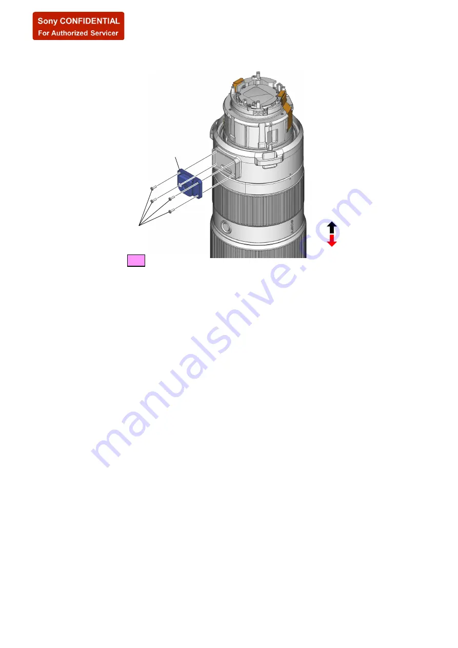
Page 50: ... 47 SEL200600G B 40 2 four screws 2 0 u 7 0 1 P Note Apply the adhesive bond to the tip of screws UHDU PRXQW VLGH IURQW OHQV VLGH 1 WULSRG SODWH 2 3 23 TRIPOD PLATE SYS SET 2019 06 28 22 04 56 GMT 09 00 ...
Page 51: ...unt side front lens side 1 rear outer ring assy rear mount side front lens side 3 tapping screw 1 4 u 3 5 1 P 3 tapping screw 1 4 u 3 5 1 P 4 Align the rear outer ring block with the position of the figure and install it index spec badge index index index 5 four screws 2 0 u 6 0 1 P 2 3 24 REAR OUTER RING ASSY SYS SET 2019 06 28 22 04 56 GMT 09 00 ...
Page 52: ...ont lens side 1 SW assy 3 Install the SW assy 2 Connect the flexible board 4 two SW plate screws L 4 5 mm 1 P Note If the paint comes off replace it with a new part without reusing it 2 3 25 SW ASSY SYS SET 2019 06 28 22 04 56 GMT 09 00 ...
Page 53: ...he space between the rear outer ring assy and the rear tube assy Note Take care not to damage the flexible board rear outer ring assy rear tube assy 3 Arrange the flexible board in the space between the rear outer ring assy and the rear tube assy Note Take care not to damage the flexible board rear outer ring assy rear tube assy 2 3 26 CL 1065 BOARD SYS SET 2019 06 28 22 04 56 GMT 09 00 ...
Page 54: ...MOUNT BLOCK rear mount side front lens side 2 contact block assy 9 mount waterproof rubber 1 mount block 5 rear shading barrel 7 conductive tape 4 tapping screw 1 4 u 2 5 1 P 6 tapping screw 1 4 u 2 5 1 P 6 tapping screw 1 4 u 2 5 1 P 6 tapping screw 1 4 u 2 5 1 P 8 Crease the contact block flexible board Mountain fold Valley fold 3 boss 2 3 27 CONTACT BLOCK ASSY MOUNT WATERPROOF RUBBER SYS SET 20...
Page 55: ...unt side front lens side 3DVWLQJ SRVLWLRQ RI WKH FDP WXEH PDVN guide line cam tube mask from front lens side 1 cam tube mask Note Be careful not to scratch the sheet 2 3 29 CAM TUBE MASK SYS SET 2019 06 28 22 04 56 GMT 09 00 ...
Page 56: ... front lens side 3 Temporarily fasten the three screws 2 0 u 6 0 2 three reinforcing plates 5 Tighten the three screws 2 0 u 6 0 1 P 1 Align the marking with the index and install the G03 assy index QVWDOODWLRQ GLUHFWLRQ IRU WKH UHLQIRUFLQJ SODWH marking rear mount side front lens side notch side QVWDOODWLRQ GLUHFWLRQ IRU WKH JURXS WLOW ZDVKHUV 2 3 30 G03 ASSY SYS SET 2019 06 28 22 04 56 GMT 09 00...
Page 57: ... plates 5 Tighten the three screws 2 0 u 6 0 1 P 1 Align the boss with the index and install the B01 assy boss index reinforcing plate rounded side face QVWDOODWLRQ GLUHFWLRQ IRU WKH UHLQIRUFLQJ SODWH rear mount side front lens side 1 group tilt washers B01 assy from front lens side notch side QVWDOODWLRQ GLUHFWLRQ IRU WKH JURXS WLOW ZDVKHUV 2 3 31 B01 ASSY SYS SET 2019 06 28 22 04 56 GMT 09 00 ...
Page 58: ...o the position in the figure and install the filter reinforcing ring index notch 2 3 33 FILTER REINFORCING RING rear mount side front lens side 2 three screws 2 0 u 6 0 1 P 1 Align the index and install the filter screw ring assy index index 2 3 32 FILTER SCREW RING ASSY SYS SET 2019 06 28 22 04 56 GMT 09 00 ...
Page 59: ...rel from the mount side and paste the protect rubber protect rubber groove groove groove groove convex part convex part convex part convex part rear mount side front lens side 1 six protect rubber adhesives filter reinforcing ring from front lens side 3 Place the lens barrel upside down 2 3 34 PROTECT RUBBER SYS SET 2019 06 28 22 04 56 GMT 09 00 ...
Page 60: ...Note 1 1 3 3 3 3 4 5 5 5 5 5 5 5 5 7 7 8 10 11 5 6 A B Refer to mount section 7 7 7 7 9 Note 2 9 Note 2 Note 1 This parts be not reused Be sure to replace them with new parts Note 2 This part is for adjustment Refer to 3 7 SELECTION PARTS and adjust the thickness by following the results of the check Ref No Part No Description Ref No Part No Description 1 500564601 PROTECT RUBBER 2 500564501 PROTE...
Page 61: ...NT ASSY 52 500623201 CONTACT BLOCK ASSY 53 500646401 1P2X6C3C NYLOK 54 500565201 MOUNT WATERPROOF RUBBER 55 500567401 LOCK PC BOARD IB 56 500564001 MAIN PC BOARD ASSY CL 1065 BOARD 57 469687101 LOCK 1P2X6C3C IB 58 500566901 SCREW SW PLATE L 4 5 mm 59 500623301 SW ASSY 60 500623001 REAR OUTER RING ASSY 61 500565001 REAR OUTER CONDUCTIN PLATE 62 468892101 BT2P1 4X3 5B3C 63 500835101 LOCK 2P2X7C3C IB...
Page 62: ...just the thickness by following the results of the check Note 3 Selection of this part is required for each unit Perform an operation check of the relevant locations refer to 3 7 SELECTION PARTS and select an appropriate part Ref No Part No Description Ref No Part No Description 101 500565101 TRIPOD RING FITTING TUBE 102 500566801 SCREW 1 GROUP PIECE 103 500622701 REAR OUTER TUBE FRONT ASSY 104 50...
Page 63: ...ickness by following the results of the check Note 2 This parts be not reused Be sure to replace them with new parts Ref No Part No Description Ref No Part No Description 151 500622201 6 GROUP ASSY 152 500565601 G24 METAL MASK 153 500567201 SCREW BT2P1 4X4 5BNI BOLT 154 469687101 LOCK 1P2X6C3C IB 155 selection parts WASHER M2 Note 1 156 269902701 BT2P1 7X5C3C 157 500623901 REAR TUBE ASSY 158 50056...
Page 64: ...ration check of the relevant locations refer to 3 7 SELECTION PARTS and select an appropriate part Ref No Part No Description Ref No Part No Description 201 500622501 MIDDLE OUTER TUBE ASSY 202 468638501 PIESE SCREW IB LOCK 203 500564801 ZOOM RUBBER 204 500564701 Z OPERATION RING 205 500835001 Z JOINT RING 206 500567001 LOCK P1 7X5 0C3C IB 207 selection parts PIECE Z JOINT Note 2 208 500565801 FRI...
Page 65: ...m an operation check of the relevant locations refer to 3 7 SELECTION PARTS and select an appropriate part Ref No Part No Description Ref No Part No Description 251 288675601 2P1 7X3 5C3C IB LOCK 252 selection parts SUB COMA Note 253 413816401 2P1 7X9C3C 254 selection parts 3RD COMA SHAFT Note 255 selection parts PIECE 3 GROUP Note 256 269902701 BT2P1 7X5C3C 257 500566501 SCREW BT1P1 7X8 0C3C 258 ...
Page 66: ...thickness by following the results of the check Thickness mm Part No 0 02 500835201 0 03 500835211 0 05 500835221 0 08 500835231 0 10 500835241 0 15 500835251 0 20 500835261 0 25 500835271 0 30 500835281 3 7 SELECTION PARTS Ref No 155 M2 WASHER This part is for adjustment Adjust the thickness by following the results of the check Thickness mm Part No 0 02 500578801 0 03 500578811 0 05 500578821 0 ...
Page 67: ...m an operation check of the relevant locations and select an appropriate part D1 D2 D1 mm D2 mm Part No 4 000 4 500 456784201 4 000 4 505 456784211 4 000 4 510 456784221 4 000 4 515 456784231 4 005 4 500 456809801 4 005 4 505 456809811 4 005 4 510 456809821 4 005 4 515 456809831 4 010 4 500 456809901 4 010 4 505 456809911 4 010 4 510 456809921 4 010 4 515 456809931 4 015 4 500 456810001 4 015 4 50...
Page 68: ... 5 525 6 010 500621031 5 525 6 015 500621041 5 525 6 020 500621051 5 525 6 025 500621061 Ref No 258 2ND COMA SHAFT Perform an operation check of the relevant locations and select an appropriate part ø 3 4 ø 4 D1 D1 mm Part No 6 000 500600901 5 990 500600911 5 980 500600921 Ref No 259 2 GROUP PIECE Perform an operation check of the relevant locations and select an appropriate part D1 D2 D1 mm D2 mm...
Page 69: ...D CHINESE 500356511 MANUAL INSTRUCTION GERMAN DUTCH SWEDISH ITALIAN PORTUGUESE Except Chinese 500356521 MANUAL INSTRUCTION RUSSIAN ARABIC TRADITIONAL CHINESE KOREAN UKRAINIAN Except Chinese 501 X25932661 CAP DIA 95 S FRONT Front lens cap 502 415970104 REAR LENS CAP 503 500622901 TRIPOD BASE ASSY Tripod collar 504 500562801 HOOD ACL SH157 Lens hood 505 500378801 STRAP 8003 Lens strap 506 500378701 ...
Page 70: ...65 Board Complete Service OpticalAxis Check Adjustment Wide z z z z z z z z z z z Resolving Power Check Partial Blur Check Wide z z z z z z z z z z z Optical Axis Check Adjustment Tele z z z z z z z z z z z Resolving Power Check Partial Blur Check Tele z z z z z z z z z z z SEL200600G_Service_Tool PRESET ADJ z z z z z z z z z z z z z z z z z z PRESET2 ADJ z z z z z F NO ADJ z z z z z z FB ADJ z z ...
Page 71: ...Resolving power check Note 5 3 Resolving power check Note 5 4 1 Partial blur adjustment B06 farame assy 5 4 2 Partial blur adjustment 6 group assy 5 2 3 Optical axis adjustment B06 farame assy 5 4 3 Partial blur adjustment G03 assy 5 2 4 Optical axis adjustment B01 assy 2 PRESET2 ADJ 3 F NO ADJ 4 FB ADJ 5 FPCA 6 Focus Shift Adjustment 7 FB CHK 8 ROM CHECK 9 SLEEP END Note Perform the Resolving Pow...
Page 72: ...type USB to serial cable Sold on the market D sub 9 pin Male Lens Test Projector F J 6082 826 A 2 E mount FF jig for Lens Test Projector F J 6082 835 A 3 For Lens Test Projector Chart E mount attachment J 6082 775 A 4 For Lens Test Projector Screen Tape measure Sold on the market Plane mirror For SLRs Camera ILCE 6300 for SEL200600G_Service_Tool General E mount Interchangeable Lens Digital Camera ...
Page 73: ...Combination of theA E mount conversion attachment and the E Mount Extension Jig A E mount conversion attachment J 6082 845 A 14 E Mount Extension Jig J 6082 799 A 15 Flange back gauge 43 50 mm J 6082 608 A 16 Extension Jig 47 00 mm J 6082 797 A 17 Resolution Check Chart ILC J 6082 813 A 18 Siemens star chart J 6080 875 A 19 Small pattern box PTB 1450 J 6082 557 A 20 Clear chart J 6082 560 A 21 For...
Page 74: ...ment B06 frame assy Use two optical axis adjustment pins Adhesive bond B 110 J 6082 617 A For partial blur adjustment B06 frame assy 5 1 4 Preparation of optical axis adjustment spring Use three optical axis adjustment spring Prepare the following part for two pieces and add processing 4 697 842 01 SPRING 8000 PRESET RING repair parts for SEL400F28GM Processing method Prepare a total of three opti...
Page 75: ... 200 FB Tester Stand Scale ring Eyepiece lens 7x Eyepiece ring 2 Looking through the eyepiece lens turn the eyepiece ring of the flange back tester so that cross line or scale in the view is the sharpest 3 Attach the flange back gauge 43 50 mm securely to theA mount attachment and hold them together 4 While applying light to the flange back gauge turn the focus ing knob of the flange back tester s...
Page 76: ... Control Box Supplied with D sub 15 pin cable AC cable Sold on the market RS 232C Cable D sub 9 pin Male with securing screws D sub 9 pin Female with securing screws Straight type Sold on the market USB to serial cable D sub 9 pin Male Sold on the market Lens adjustment program BLG TestProgramV exe See Note 2 Note 1 Personal computer must have the condition that Windows 7 runs normally and USB is ...
Page 77: ...Power button is made active When the password input window opens ask service head quarters about password In this case the ID shown in COM USER Characteristic Number must be informed YdDGAAHTJ in the example above Since this ID number is unique to the B L Control Box and personal computer if used another B L Control Box or per sonal computer another password is necessary 5 Connection to the lens m...
Page 78: ...s At this time confirm that both of the two LEDs on the B L Control Box are light If either or none of them does not light there is a problem LEDs for power supply check B L Control Box Power switch Note 1 Before detaching the lens after power is supplied be sure to click Power again and confirm that the two LEDs go out 9 Select Center Hold from the steady shot selection menu and click Steady Shot ...
Page 79: ...light position is deviated re adjust the lens projector position 11 Select Open from the iris selection menu and click Iris Iris setting Open 12 Rotate the zooming ring of the checking lens set the zoom position Note 2 This lens is not power zoom do not use the following zoom operation Zoom operation 13 Select from the focus selection menu Focus setting SYS SET 2019 06 28 22 04 56 GMT 09 00 ...
Page 80: ...maximum flare is in the sharpest focus as shown with the arrow in Fig e and then read the dial gauge value C 5 Turn the focusing knob until the ring chart edge opposite 180 degrees from the above step 4 condition as shown with the arrow in Fig f is in focus and then read the dial gauge value D 6 Calculate the CB value absolute difference between C and D and check that it is within the specification C...
Page 81: ...ng a B L Control Box and set the 1000 mm collimator 11 Set the zoom to the WIDE end 12 Adjust the optical axis by increase or decrease the thickness of the B06 frame washer so that the ring chart image is centered while looking at the 1000 mm collimator B06 frame washer B06 frame washer B06 frame washer B06 FRAME WASHER Thickness mm Part No 0 02 500835201 0 03 500835211 0 05 500835221 0 08 5008352...
Page 82: ... Box and set the 1000 mm collimator 4 Set the zoom to the TELE end 5 Adjust the optical axis by increase or decrease the thickness of the 1 group tilt washer so that the ring chart image is centered while looking at the 1000 mm collimator 1 group tilt washer 1 group tilt washer 1 group tilt washer 1 group tilt washer from front lens side notch side 1 GROUP TILT WASHER Thickness mm Part No 0 02 500...
Page 83: ...2 Attach the checking lens to the Lens Test Projector and set the equipment as shown in the figure below 3 Set the zoom to the arbitrary position 4 Turn ON the main switch of the Lens Test Projector 5 Turn ON the lamp switch of the Lens Test Projector 6 To set the lens surface and the screen in parallel align the plane mirror with the center projected image on the screen and adjust the lens projec...
Page 84: ...C to the Lens Test Projector 1 Setting of Lens Test Projector Setting Procedure 1 Connect the B L Control Box with the personal computer and the Lens Test Projector 2 Attach the checking lens to the Lens Test Projector and set the equipment as shown in the figure below 3 Turn ON the main switch of the Lens Test Projector 4 Turn ON the lamp switch of the Lens Test Projector 5 To set the lens surfac...
Page 85: ... case the ID shown in COM USER Characteristic Number must be informed YdDGAAHTJ in the example above Since this ID number is unique to the B L Control Box and personal computer if used another B L Control Box or per sonal computer another password is necessary 5 Connection to the lens mount block is established and the Power button is made active Procedure of Finishing 1 Click Power to turn off th...
Page 86: ...o the checking lens At this time confirm that both of the two LEDs on the B L Control Box are light If either or none of them does not light there is a problem LEDs for power supply check B L Control Box Power switch Note 1 Before detaching the lens after power is supplied be sure to click Power again and confirm that the two LEDs go out 4 Select Center Hold from the steady shot selection menu and ...
Page 87: ...d re adjust the lens projector position 6 Select Open from the iris selection menu and click Iris Iris setting Open 7 Rotate the zooming ring of the checking lens set the zoom position Note 2 This lens is not power zoom do not use the following zoom operation Zoom operation 8 Select JOG from the focus menu Not used this section Check off Use this section Continued on next page SYS SET 2019 06 28 2...
Page 88: ...ect focus step value Select and enter focus step speed Focus drive near Focus drive far Focus position indicator 10 Adjust the focus position with Near and Far while selecting Focus Step and Low Mid High and then click OK to close the focus JOG window SYS SET 2019 06 28 22 04 56 GMT 09 00 ...
Page 89: ...50 10 0 300 12 0 400 16 0 500 20 0 600 24 0 Checking Procedure 1 Set the projection distance of the lens projector Refer to Reference value 2 Set the focus 3 Bring the projector into focus so that fine lines of the center projected image y 0 on the screen can be clearly seen as much as possible by operating the program screen Saggital S Meridional M The number of projective resolving power lines U...
Page 90: ...yond resolving power are visible as black and white stripes as if resolution is made In this case black and white of three stripes are reversed and seen as if they are two or four lines in some cases Be careful not to confuse this phenomenon with the resolution limit Correct resolution Spurious resolution 6 Change the focal length and projection distance of the checking lens and confirm that the n...
Page 91: ...rthermore move it to the 100 mm rear from that position 0 8 0 6 0 5 0 3 0 3 0 5 0 6 0 8 2 Checking Method Checking Procedure 1 Set to manual focus on status that the 1 Setting of Equipment condition 2 Focus and shoot with self timer 3 Keep focusing as step 2 change the object distance to the shooting distance position 100 mm of step 1 then shoot two times with self timer 4 Check the three images t...
Page 92: ...ens side and move the B06 frame assy little by little Perform the check and adjustment repeatedly until the partial blur is improved 3 When partial blur is improved 5 2 2 Optical Axis Check is performed to check that the optical axis of checking lens satisfies the specification 4 Remove the rear tube assy referring to the 2 2 DISASSEM BLY 5 After removing the optical axis adjustment spring tighten...
Page 93: ...r Adjustment G03 assy Note Partial Blur Adjustment G03 assy is done by increasing or de creasing the thickness of the washer Refer to 2 2 DISASSEMBLY disassemble the lens and change the thickness of the washer Adjusting Procedure 1 Remove the filter screw ring assy referring to the 2 2 DISAS SEMBLY 2 Loosen the three screws to fixing the G03 assy 3 Increase or decrease the thickness of the 1 group...
Page 94: ...ld be 200 to 400 lux or 35 to 65 cd m2 Please make the FB adjustment chart so that there is no un evenness of light source 5 5 1 Preparations Set the equipment and the checking lens as shown below Shoot the small pattern box so that the screen becames fully white When the subject is a small pattern box Small pattern box PTB 1450 clear chart Cover with a blackout curtain Siemens star chart Siemens ...
Page 95: ...rs then select the installing user and click the Next button Everyone The application will be installed for all users Just me The application will only be installed for the current user 5 The installer confirm screen appears then click the Next button to start the installation 6 The following screen appears when the installation is complete then click the Close button 7 Create a shortcut icon of t...
Page 96: ...setup exe file 3 The installer screen appears then click the Next button 4 The folder select screen appears then select the installing user and click the Next button Everyone The application will be installed for all users Just me The application will only be installed for the current user 5 The installer confirm screen appears then click the Next button to start the installation 6 The following s...
Page 97: ...click the Next button Everyone The application will be installed for all users Just me The application will only be installed for the current user 5 The installer confirm screen appears then click the Next button to start the installation 6 The following screen appears when the installation is complete then click the Close button 7 Create a folder of C Service FSA SEL200600G_FSA in C drive and sto...
Page 98: ... adjustment including the case when stops due to an error SeusEX will start when the SEL200600G_Service_Tool is started Procedure of Starting 1 Set the Shooting Mode of the camera to the P mode Program Auto then turn the power on 2 Start the ServiceAppLauncher Note If the message as shown below is displayed confirm that the following a file is stored in C Service ErrorCodeList folder of the C drive ...
Page 99: ...mera P mode Program Auto Preparations In the PRESET ADJ it is necessary to rotate the focusing ring in accurately one rotation when adjust inspection Please stick the tape etc for checking the initial position of the focusing ring Tape etc When rotating the focusing ring it is necessary to keep rotating at a constant speed Place the lens body on the front side facing down and rotate the focusing r...
Page 100: ...r 6 Message screen is displayed in the following order Operate the SteadyShot switch in accordance with the message SteadyShot switch 7 Message screen is displayed in the following order Operate the SteadyShot mode switch in accordance with the message SteadyShot mode switch 8 After the switch inspection is completed starts the focusing ring adjust inspection FOCUS RING ADJUSTMENT START is display...
Page 101: ...g adjust inspection is completed automati cally starts the each adjustments hall sensor adjust MR sensor adjust 16 When the automatic adjustment is completed message screen is displayed in the following Use a tripod to set the lens in a stable horizontal condition 17 When the ENTER key is pressed message screen is displayed in the following Repeatedly set the zooming ring to the WIDE end TELE end ...
Page 102: ... is displayed in the following Set the zooming ring to the TELE end focal length 600 mm Zooming ring 21 When the ENTER key is pressed automatically starts the each adjustments and inspections mechanical end adjust PWM ad just electric current self diagnosis actuator damage inspection 22 After the each adjustments is completed starts the horizontal adjustment Place the lens horizontally is displaye...
Page 103: ...d Inspection 2 Set to WIDE is displayed set the zooming ring to the WIDE end focal length 200 mm Zooming ring 3 Select the AF is displayed set the focus mode switch to the AF Focus mode switch 4 When the focus lens stops press the Enter button is displayed confirm that the screen is fully white and press the ENTER key 5 When the ENTER key is pressed automatically starts the adjust ments 6 When F n...
Page 104: ...is displayed and after the preparation of adjustment is completed press the ENTER key 3 Select the AF is displayed set the focus mode switch to the AF Focus mode switch 4 PLEASE CHANGE TO WIDE is displayed set the zooming ring to the WIDE end focal length 200 mm Zooming ring 5 When the ENTER key is pressed automatic adjustment of WIDE end is started Note 2 When the error occurs in the flange back a...
Page 105: ...e operations from step 8 to step 10 to POS8 13 After the automatic adjustment of POS8 is completed message screen is displayed in the following Set the zooming ring to the TELE end focal length 600 mm Zooming ring 14 Rotate the zooming ring to the WIDE side until the background color of the value hexadecimal number at the lower left of the window changes to light blue 15 When the ENTER key is pres...
Page 106: ...ight source Adjusting Method 1 Click the FPCA button in the Adjustment and Inspection 2 The START screen is displayed and after the preparation of adjustment is completed press the ENTER key 3 PLEASE CHANGE ZOOM to TELE is displayed set the zooming ring to the TELE end focal length 600 mm Zooming ring 4 When the ENTER key is pressed focus position compensation adjustment is started 5 When focus po...
Page 107: ...art so that there is no un evenness of light source Siemens star chart Screen display Finite_3m Siemens star chart Image sensor position mark 3 m Checking lens Adjusting Method 1 Click the FSA button in the Adjustment and Inspection 2 The START screen is displayed and after the preparation of adjustment is completed press the ENTER key 3 Select the AF is displayed set the focus mode switch to the ...
Page 108: ... star chart on the subject 13 When the ENTER key is pressed automatic adjustment is started 14 After the automatic adjustment is completed the calculation processing of the quantity of correction is started The display of the message screen changes as follows 15 When calculation processing of the quantity of correction is completed FSAADJUSTMENT OK is displayed 16 When the ENTER key is pressed rec...
Page 109: ... Adjustment and Inspection 2 PLEASE CHANGE ZOOM to TELE is displayed set the zooming ring to the TELE end focal length 600 mm Zooming ring 3 Select the AF is displayed set the focus mode switch to the AF Focus mode switch 4 Confirm the image is in focus while zoom Start is displayed press the ENTER key 5 While operating the zooming ring check that the FB adjustment chart is in sharpest focus on th...
Page 110: ...ch Focus range limiter SteadyShot switch SteadyShot mode switch Zooming ring Shooting Mode of the camera P mode Program Auto Checking Method 1 Set the switch position of the lens as follows Focus mode switch AF Focus range limiter FULL SteadyShot switch ON SteadyShot mode switch MODE1 2 Click the SLEEP button in the Adjustment and Inspection 3 PLEASE CHANGE ZOOM TO WIDE is displayed set the zoomin...
Page 111: ... displayed in the serial number display field Serial number display field 11 Check the log information It can save check the log information of the Main board Subject Not required Operation on Lens side Not required Shooting Mode of the camera P mode Program Auto Saving Method 1 Click the EEPROM read ALL button in the Adjustment and Inspection 2 The folder browsing dialog is displayed select the f...
Page 112: ...Revision History SEL200600G Ver Date History Contents 1 0 2019 06 Official Release SYS SET 2019 06 28 22 04 56 GMT 09 00 ...