


7-2
7-2. ADJUSTMENT OF VIDEO SYSTEM
1. Video Level Adjustment (MB-85 BOARD)
<Purpose>
This adjustment is made to satisfy the NTSC standard, and if not
adjusted correctly, the brightness will be too large or small.
Mode
Video level adjustment in test mode
Signal
Color bars
Test point
LINE OUT (VIDEO) connector
(75
Ω
terminated)
Instrument
Oscilloscope
Adjusting element
RV401
Specification
1.0 ± 0.02 Vp-p
Adjusting method:
1) In the test mode initial menu “6” Video Level Adjustment, set
so that color bars are generated.
2) Adjust the RV401 to attain 1.0 ± 0.02 Vp-p.
Figure 7-1
2. S-terminal Output Check (MB-85 BOARD)
<Purpose>
Check S-terminal video output. If it is incorrect, pictures will not
be displayed correctly in spite of connection to the TV with a S-
terminal cable.
Mode
Video level adjustment in test mode
Signal
Color bars
Test point
S VIDEO OUT (S-Y) connector
(75
Ω
terminated)
Instrument
Oscilloscope
Specification
1.0 ± 0.1 Vp-p
Checking method:
1) In the test mode initial menu “6” Video Level Adjustment, set
so that color bars are generated.
2) Confirm that the S-Y level is 1.0 ± 0.1 Vp-p.
Figure 7-2
3. Checking Component Video Output B-Y
(MB-85 BOARD)
<Purpose>
This checks component video output B-Y. If it is incorrect, cor-
rect colors will not be displayed when connected to, for instance,
projector.
Mode
Video level adjustment in test mode
Signal
Color bars
Test point
COMPONENT VIDEO OUT (B-Y)
connector (75
Ω
terminated)
Instrument
Oscilloscope
Specification
700 ± 70 mVp-p
Checking method:
1) Confirm that the B-Y level is 700 ± 70 mVp-p.
Figure 7-3
4. Checking Component Video Output R-Y
(MB-85 BOARD)
<Purpose>
This checks component video output R-Y. If it is incorrect, cor-
rect colors will not be displayed when connected to, for instance,
projector.
Mode
Video level adjustment in test mode
Signal
Color bars
Test point
COMPONENT VIDEO OUT (R-Y)
connector (75
Ω
terminated)
Instrument
Oscilloscope
Specification
700 ± 70 mVp-p
Checking method:
1) Confirm that the R-Y level is 700 ± 70 mVp-p.
Figure 7-4
700 ± 70 mVp-p
1.0 ± 0.02 Vp-p
1.0 ± 0.1 Vp-p
700 ± 70 mVp-p
Summary of Contents for DVP-S533
Page 7: ...1 2 ...
Page 8: ...1 3 ...
Page 9: ...1 4 ...
Page 10: ...1 5 ...
Page 11: ...1 6 ...
Page 12: ...1 7 ...
Page 13: ...1 8 ...
Page 14: ...1 9 ...
Page 15: ...1 10 ...
Page 16: ...1 11 ...
Page 17: ...1 12 ...
Page 18: ...1 13 ...
Page 19: ...1 14 1 14 E ...
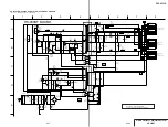
Page 34: ...DVP S533D 4 3 4 4 4 1 FRAME SCHEMATIC DIAGRAM FRAME 1 SCHEMATIC DIAGRAM FRAME 1 2 ...
Page 35: ...DVP S533D FRAME 2 SCHEMATIC DIAGRAM 4 5 4 6 FRAME 2 2 ...