


2-2
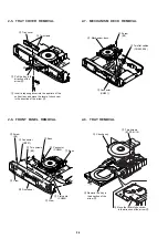
2-5. TRAY COVER REMOVAL
2-7. MECHANISM DECK REMOVAL
2-6. FRONT PANEL REMOVAL
2-8. TRAY REMOVAL
4
Tray cover
2
Pull the tray in the
direction of the
arrow
B
.
1
Insert a tapering driver into the aperture of the
unit bottom, and move the lever of chuck cam
in the direction of the arrow
A
.
3
Two claws
B
A
4
Screw
(B3)
2
Connector
(CN701)
3
Flat cable
(CN006)
1
Connector
(CN203)
5
Two screws
(B3)
9
Claw
8
Claw
!º
Front panel
6
Boss
7
Boss
2
Two flat cables
(CN003, 004)
3
Screw
(B3)
4
Mechanism deck
1
Connector
(CN001)
2
Chuck ass’y
4
Remove the tray in
the direction of the
arrow
B
.
3
Move the lever of chuck cam
in the direction of the arrow
A
.
1
Two screws
(BTP2.6
×
12)
B
A
Summary of Contents for DVP-S533
Page 7: ...1 2 ...
Page 8: ...1 3 ...
Page 9: ...1 4 ...
Page 10: ...1 5 ...
Page 11: ...1 6 ...
Page 12: ...1 7 ...
Page 13: ...1 8 ...
Page 14: ...1 9 ...
Page 15: ...1 10 ...
Page 16: ...1 11 ...
Page 17: ...1 12 ...
Page 18: ...1 13 ...
Page 19: ...1 14 1 14 E ...
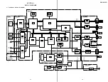
Page 34: ...DVP S533D 4 3 4 4 4 1 FRAME SCHEMATIC DIAGRAM FRAME 1 SCHEMATIC DIAGRAM FRAME 1 2 ...
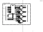
Page 35: ...DVP S533D FRAME 2 SCHEMATIC DIAGRAM 4 5 4 6 FRAME 2 2 ...