– 9 –
7-4.
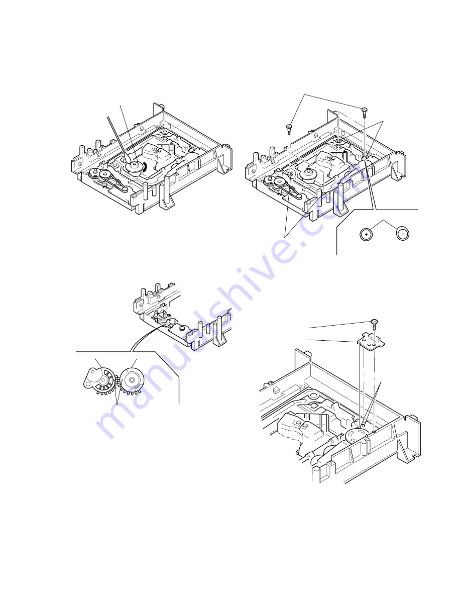
Deformation of Insulator
1) Assemble the spindle base into the base unit.
2) Lock with 4 shoulder screws. (See Fig. 11)
3) Check if 4 insulators deformed. (See Fig. 11)
Fig. 11
7-5.
Note on Mounting FG-43 Board
1) Align two bosses. (See Fig. 12)
2) Fix the board securely with screws (PTPWH2
×
5). (The sen-
sor will not function normally if the board floats up.)
Fig. 12
7-2.
Cleaning Spindle Motor Turntable
1) Remove the tray. (Refer to 2-7)
2) Clean the spindle motor turntable if disc antiskid rubber (black)
is dirty. (See Fig. 9)
Fig. 9
7-3.
Aligning Phase of Cam Gear and
Drive Gear
1) Align triangle marks when assembling the cam gear and drive
gear. (See Fig. 10)
Fig. 10
Spindle motor
Turntable
Four step screws
Two insulators
Two insulators
Insulator
Good
NG
Drive gear
Cam gear
Align triangle marks.
Screw
(PTPWH2
×
5)
FG-43 board
Two bosses
Summary of Contents for DVP-S300
Page 12: ...1 2 ...
Page 13: ...1 3 ...
Page 14: ...1 4 ...
Page 15: ...1 5 ...
Page 16: ...1 6 ...
Page 17: ...1 7 ...
Page 18: ...1 8 ...
Page 19: ...1 9 ...
Page 20: ...1 10 1 10 E ...
Page 49: ...7 5 E 1 2 10 12 14 24 25 CN252 MB 78 BOARD Side B ...

