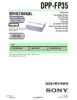
background image

— 3 —

DPP-FP35

1.

Check the area of your repair for unsoldered or poorly-soldered
connections.  Check the entire board surface for solder splashes
and bridges.

2.

Check the interboard wiring to ensure that no wires are
"pinched" or contact high-wattage resistors.

3.

Look for unauthorized replacement parts, particularly
transistors, that were installed during a previous repair.  Point
them out to the customer and recommend their replacement.

4.

Look for parts which, through functioning, show obvious signs
of deterioration.  Point them out to the customer and
recommend their replacement.

5.

Check the B+ voltage to see it is at the values specified.

6.

Flexible Circuit Board Repairing

• Keep the temperature of the soldering iron around 270˚C

during repairing.

• Do not touch the soldering iron on the same conductor of the

circuit board (within 3 times).

• Be careful not to apply force on the conductor when soldering

or unsoldering.

Unleaded solder

Boards requiring use of unleaded solder are printed with the lead-
free mark (LF) indicating the solder contains no lead.
(Caution: Some printed circuit boards may not come printed with
the lead free mark due to their particular size.)

 : LEAD FREE MARK

Unleaded solder has the following characteristics.
• Unleaded solder melts at a temperature about 40

°

C higher than

ordinary solder.
Ordinary soldering irons can be used but the iron tip has to be
applied to the solder joint for a slightly longer time.
Soldering irons using a temperature regulator should be set to
about 350

°

C.

Caution: The printed pattern (copper foil) may peel away if the
heated tip is applied for too long, so be careful!

• Strong viscosity

Unleaded solder is more viscous (sticky, less prone to flow) than
ordinary solder so use caution not to let solder bridges occur such
as on IC pins, etc.

• Usable with ordinary solder

It is best to use only unleaded solder but unleaded solder may
also be added to ordinary solder.

SAFETY CHECK-OUT

After correcting the original service problem, perform the following

safety checks before releasing the set to the customer.

SAFETY-RELATED COMPONENT WARNING!!

COMPONENTS IDENTIFIED BY MARK 

0

 OR DOTTED LINE WITH

MARK 

0

 ON THE SCHEMATIC DIAGRAMS AND IN THE PARTS

LIST ARE CRITICAL TO SAFE OPERATION. REPLACE THESE
COMPONENTS WITH SONY PARTS WHOSE PART NUMBERS
APPEAR AS SHOWN IN THIS MANUAL OR IN SUPPLEMENTS
PUBLISHED BY SONY.

ATTENTION AU COMPOSANT AYANT RAPPORT

À LA SÉCURITÉ!

LES COMPOSANTS IDENTIFÉS PAR UNE MARQUE 

0

 SUR LES

DIAGRAMMES SCHÉMATIQUES ET LA LISTE DES PIÈCES SONT
CRITIQUES POUR LA SÉCURITÉ DE FONCTIONNEMENT. NE
REMPLACER CES COMPOSANTS QUE PAR DES PIÈSES SONY
DONT LES NUMÉROS SONT DONNÉS DANS CE MANUEL OU
DANS LES SUPPÉMENTS PUBLIÉS PAR SONY.

Summary of Contents for DPP-FP35

Page 1: ...istory Ver 1 1 2007 02 Sony EMCS Co 2007B1600 1 2007 02 Published by Kohda TEC 9 852 132 12 DPP FP35 DPP FP35 How to use Acrobat Reader How to use Acrobat Reader SPECIFICATIONS REPAIR PARTS LIST SERVICE NOTE When the parts other than those described in 2 Repair Parts List need replacement replace the unit Revised 1 Replace the previously issued SERVICE MANUAL 9 852 132 11 with this Manual ...

Page 2: ...N jack DC 24 V On standby mode less than 1W Operating temperature 5 C to 35 C 41 F to 95 F Dimensions Approx 175 x 60 x 137 mm 7 x 2 3 8 x 5 1 2 inches w h d excluding protruding parts 306 mm 12 1 8 inches of depth when the paper tray is installed Mass Approx 1 kg 2 lb 3 oz excluding the paper tray print cartridge AC power adaptor Supplied accessories See page 1 3E x Printer Printing method Dye su...

Page 3: ...r melts at a temperature about 40 C higher than ordinary solder Ordinary soldering irons can be used but the iron tip has to be applied to the solder joint for a slightly longer time Soldering irons using a temperature regulator should be set to about 350 C Caution The printed pattern copper foil may peel away if the heated tip is applied for too long so be careful Strong viscosity Unleaded solder...

Page 4: ... 4 DPP FP35 TABLE OF CONTENTS 1 SERVICE NOTE 1 1 2 REPAIR PARTS LIST 2 1 EXPLODED VIEWS 2 2 ...

Page 5: ...1 1E DPP FP35 1 SERVICE NOTE When you re assembling the thermal printer install it in the direction of the arrow thermal printer ...

Page 6: ...NOTE NOTE DPP FP35 Link Link 2 REPAIR PARTS LIST EXPLODED VIEWS EXPLODED VIEWS OVERALL SECTION ACCESSORIES ACCESSORIES ...

Page 7: ...s in the parts list may be different from the parts specified in the diagrams or the components used on the set CAPACITORS uF µF COILS uH µH RESISTORS All resistors are in ohms METAL metal film resistor METAL OXIDE Metal Oxide film resistor F nonflammable SEMICONDUCTORS In each case u µ for example uA µA uPA µPA uPB µPB uPC µPC uPD µPD When indicating parts by reference number please include the b...

Page 8: ...2 3 254 070 01 SCREW 3 2 190 483 01 FOOT RUBBER 4 7 682 545 04 B 3X4 5 2 676 797 01 LID MEDIA 6 2 676 795 01 CASE LOWER 7 3 254 140 01 SCREW B2 6 BV TAPPING 8 2 676 799 01 SUPPORT FAN 9 2 677 204 01 LID UPPER 10 2 677 207 01 SHEET ORNAMENT ADHESIVE 11 2 677 206 01 ORNAMENT AEP UK EE RUS 11 2 677 206 11 ORNAMENT US CND E AUS KR 12 X 2149 226 1 BUTTON STANDBY ASSY SERVICE 13 2 685 098 01 ILLUMINATOR...

Page 9: ...OPERATING INSTRUCTIONS SPANISH AEP E 2 682 260 71 OPERATING INSTRUCTIONS PORTUGUESE AEP E 2 682 260 81 OPERATING INSTRUCTIONS RUSSIAN EE RUS 2 682 260 91 OPERATING INSTRUCTIONS ARABIC E 2 682 261 11 OPERATING INSTRUCTIONS PERSIAN E 2 682 261 21 OPERATING INSTRUCTIONS KOREAN KR 2 682 262 11 QUICK START GUIDE ENGLISH US CND AEP UK E AUS EE RUS 2 682 262 21 QUICK START GUIDE FRENCH CND AEP 2 682 262 ...

Page 10: ...pplied to the Service Manual depending on the date of issue Switching a page To move to the first page click the To move to the last page click the To move to the previous page click the To move to the next page click the Reversing the screens displayed once To reverse the previous screens operation one by one click the To advance the reversed screens operation one by one click the Application to ...

Page 11: ...Revision History 985213212 pdf DPP FP35 Ver 1 0 1 1 Date 2006 06 2007 02 History Official Release Revised 1 Contents Change of repair parts list S M Rev issued Yes Reverse ...

Reviews: