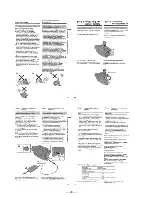
— 9 —
2.
DISASSEMBLY
The following flow chart shows the disassembly procedure.
DCR-TR
V130E
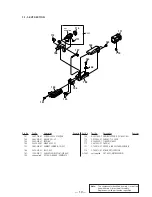
2-1. Video light
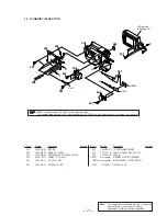
2-2. LCD section (PD-131 board)
2-3. Front panel section (MI-041 board)
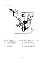
2-4. Cabinet (L) section
2-7, Battery panel section (Battery terminal board)
2-8, Lens section
2-9. VC-256 board
2-10. Mechanism deck
2-5. Cabinet (R) section, Control switch block (CF-1000)
2-6. EVF section (VF-129 board)
2-11. Hinge section
Summary of Contents for Digital Handycam DCR-TRV130E
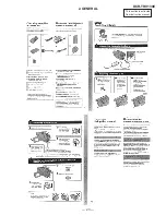
Page 23: ...This section is extracted from instruction manual 23 DCR TRV130E 2 GENERAL ...
Page 24: ... 24 ...
Page 25: ... 25 ...
Page 26: ... 26 ...
Page 27: ... 27 ...
Page 28: ... 28 ...
Page 29: ... 29 ...
Page 30: ... 30 ...
Page 31: ... 31 ...
Page 32: ... 32 ...
Page 33: ... 33 ...
Page 34: ... 34 ...
Page 35: ... 35 ...
Page 36: ... 36 ...
Page 37: ... 37 ...
Page 38: ... 38 ...
Page 39: ... 39 ...
Page 40: ... 40 ...
Page 41: ... 41 ...
Page 42: ... 42 ...
Page 43: ... 43 ...
Page 44: ... 44 ...
Page 45: ... 45 ...
Page 46: ... 46 ...
Page 47: ... 47 ...
Page 48: ... 48 ...
Page 49: ... 49 ...
Page 50: ... 50 ...
Page 51: ... 51 ...


