— 13 —
2-6.
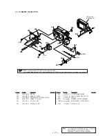
EVF SECTION (VF-129 BOARD)
2
Three tapping
screws (B2
×
5)
3
EVF section
2
Two tapping
screws (B2
×
5)
1
VF hinge assembly
1
FFC-289 flexible
flat cable (4P)
FFC-289 flexible
flat cable
2
Two loose
stopper screws
(M2
×
3)
1
Tape (A)
4
4
Tape (A)
3
VF base B
1
F lock
screw (T)
1
2
Slide the button in the
direction of the arrow
A
.
2
Two tapping
screws
(B2
×
5)
5
Tapping screw
(B2
×
5)
6
EVF tally
7
EVF cabinet lower B
3
Claw
8
CRT assembly, VF-129 board,
FFC-289 flexible flat cable
4
EVF cabinet
upper B assembly
A
B
C
3
Finder (S) assembly
Rotate it in the direction of
the arrow
B
and remove it
in the direction of the arrow
C
.
PRECAUTION DURING
INSTALLATION
Summary of Contents for Digital Handycam DCR-TRV130E
Page 23: ...This section is extracted from instruction manual 23 DCR TRV130E 2 GENERAL ...
Page 24: ... 24 ...
Page 25: ... 25 ...
Page 26: ... 26 ...
Page 27: ... 27 ...
Page 28: ... 28 ...
Page 29: ... 29 ...
Page 30: ... 30 ...
Page 31: ... 31 ...
Page 32: ... 32 ...
Page 33: ... 33 ...
Page 34: ... 34 ...
Page 35: ... 35 ...
Page 36: ... 36 ...
Page 37: ... 37 ...
Page 38: ... 38 ...
Page 39: ... 39 ...
Page 40: ... 40 ...
Page 41: ... 41 ...
Page 42: ... 42 ...
Page 43: ... 43 ...
Page 44: ... 44 ...
Page 45: ... 45 ...
Page 46: ... 46 ...
Page 47: ... 47 ...
Page 48: ... 48 ...
Page 49: ... 49 ...
Page 50: ... 50 ...
Page 51: ... 51 ...


