


5-32
2. D range Adjustment (PD-110 board)
Set the D range of the RGB decoder used to drive the LCD to the
specified value. If deviated, the LCD screen will become blackish
or saturated (whitish).
Mode
Camera
Subject
Arbitrary
Measurement Point
Pin
7
of CN2904 (PD VG) on
VC-217 board
Measuring Instrument
Oscilloscope
Adjustment Page
D
Adjustment Address
82
Specified Value
A = 3.45 ± 0.05V
Adjusting method:
1)
Select page: 0, address: 01, and set data: 01.
2)
Select page: 3, address: 0C, set data: 20, and press the PAUSE
button of the adjustment remote commander.
3)
Select page: 3, address: 22, set data: 02, and press the PAUSE
button of the adjustment remote commander.
4)
Select page: D, address: 82, change the data and set the voltage
(A) between the reversed waveform pedestal and non-reversed
waveform pedestal to the specified value.
5)
Press the PAUSE button of the adjustment remote commander.
6)
Select page: 3, address: 22, set data: 00, and press the PAUSE
button of the adjustment remote commander.
7)
Select page: 3, address: 0C, set data: 00, and press the PAUSE
button of the adjustment remote commander.
8)
Select page: 0, address: 01, and set data: 00.
3. Bright Adjustment (PD-110 board)
Set the level of the VIDEO signal for driving the LCD to the specified
value. If deviated, the screen image will be blackish or saturated
(whitish).
Mode
Camera
Subject
Arbitrary
Measurement Point
Pin
7
of CN2904 (PD VG) on
VC-217 board
Measuring Instrument
Oscilloscope
Adjustment Page
D
Adjustment Address
8A
Specified Value
A = 1.70 ± 0.05V
Adjusting method:
1)
Select page: 0, address: 01, and set data: 01.
2)
Select page: 3, address: 0C, set data: 20, and press the PAUSE
button of the adjustment remote commander.
3)
Select page: 3, address: 22, set data: 02, and press the PAUSE
button of the adjustment remote commander.
4)
Select page: 2, address: 0E, and set data: 40.
5)
Select page: D, address: 8A, change the data and set the voltage
(A) between the pedestal and GAMMA1 limiter level to the
specified value. (The data of address: 8A should be “1E” to
“A0”.)
6)
Press the PAUSE button of the adjustment remote commander.
7)
Select page: 2, address: 0E, and set data: 00.
8)
Select page: 3, address: 22, set data: 00, and press the PAUSE
button of the adjustment remote commander.
9)
Select page: 3, address: 0C, set data: 00, and press the PAUSE
button of the adjustment remote commander.
10) Select page: 0, address: 01, and set data: 00.
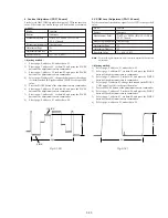
Fig. 5-1-18.
Fig. 5-1-19.
Pedestal
A
2H
Pedestal
Pedestal
A
2H
GAMMA 1 limiter lavel
Summary of Contents for Digital Handycam DCR-TRV10
Page 10: ...1 2 ...
Page 11: ...1 3 ...
Page 12: ...1 4 ...
Page 13: ...1 5 ...
Page 14: ...1 6 ...
Page 15: ...1 7 ...
Page 16: ...1 8 ...
Page 17: ...1 9 ...
Page 18: ...1 10 ...
Page 19: ...1 11 ...
Page 20: ...1 12 ...
Page 21: ...1 13 ...
Page 22: ...1 14 ...
Page 23: ...1 15 ...
Page 24: ...1 16 ...
Page 25: ...1 17 ...
Page 26: ...1 18 ...
Page 27: ...1 19 ...
Page 28: ...1 20 ...
Page 29: ...1 21 ...
Page 30: ...1 22 ...
Page 31: ...1 23 ...
Page 32: ...1 24 ...
Page 33: ...1 25 ...
Page 34: ...1 26 ...
Page 35: ...1 27 ...
Page 36: ...1 28 ...
Page 37: ...1 29 ...
Page 38: ...1 30 ...
Page 39: ...1 31 ...
Page 40: ...1 32 ...
Page 41: ...1 33 ...
Page 42: ...1 34 ...
Page 43: ...1 35 ...
Page 44: ...1 36 ...
Page 45: ...1 37E ...
Page 57: ...DCR TRV8 TRV8E TRV10 TRV10E 3 5 3 6 3 7 3 8 3 2 OVERALL BLOCK DIAGRAM TRV10 TRV10E ...
Page 58: ...DCR TRV8 TRV8E TRV10 TRV10E 3 3 POWER BLOCK DIAGRAM 3 9 3 10 3 11 3 12E ...
Page 180: ... 264 OPTICAL AXIS FRAME Take a copy of OPTICAL AXIS FRAME with a clear sheet for use ...


