DCR-IP45/IP45E/IP55/IP55E
COVER
COVER
4-2. SCHEMATIC DIAGRAMS
4-3. PRINTED WIRING BOARDS
4-2. SCHEMATIC DIAGRAMS
4-3. PRINTED WIRING BOARDS
4-91
4-92
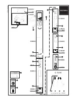
VF-154 (BACK LIGHT) PRINTED WIRING BOARD
VF-154
MOUNTED PARTS LOCATION
MOUNTED PARTS LOCATION
For printed wiring boards
• Refer to page 4-108 for parts location.
• This board is eight-layer print board. However, the pat-
terns of layers two to seven have not been included in
the diagram.
There are a few cases that the part printed on
this diagram isn’t mounted in this model.
•
: Uses unleaded solder.