3
SECTION 1
SERVICING NOTE
This unit cannot be repaired by itself.
When repairing, connect the whole system except for the speaker.
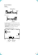
MC Test Mode
Procedure :
1. When the power ON, press the
?
/
1
button (TA) while pressing TUNING MODE button (ST) and REPEAT button (CDP) together.
2. Frame of the MD mark and the CD mark flash, and “BASS/TRE FLAT” appears for a moment.
3. When the VOLUME knob (TA) is turned clockwise, “VOLUME MAX” appears for a moment.
4. When the VOLUME knob (TA) is turned counterclockwise, “VOLUME MIN” appears for a moment.
5. Select the function “TAPE” using the FUNCTION knob (TA).
Set the test tape AMS-110A or AMS-120.
6. Press DIRECTION button (TC) to enter either “
j
” (loop) or “
h
” (two way).
7. Press the CD SYNC REC button (TC) to start the AMS test.
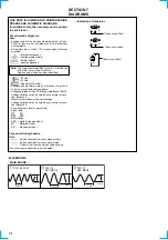
8. Number of AMS signals is counted during the AMS test and the message “EDG#” (# means a number) appears. When the test tape
either AMS-110A or AMS-120 is used, the AMS signal is detected twice before shut off.
9. When the AMS test ends, either “OK” or “NG” appears.
10.To exit the MC test mode, either press the
?
/
1
button (TA) or perform the cold reset as described above.
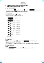
(FWD) REW
(Shut off)
(FWD) FF AMS
(FWD) REW AMS
END
(Shut off)
(Shut off)
Cold Reset
• When the AC cord is removed, COLD RESET is done with TC-SP55.
ST Test Mode
Procedure :
1. When the power ON, press the
?
/
1
button (TA) while pressing the TUNING MODE button (ST) and PLAY MODE buttons (CDP)
together.
2. LCD are all turned on.
3. Press TUNING MODE button (ST) to enter the model destination indecation mode. “SP55 CE2” or “SP55 ASIA2” appears.
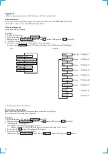
4. Every pressing of TUNING MODE button (ST) changes the display in the following order.
MC Version
t
CD Version
t
ST Version
t
TC Version
t
TA Version
t
TM Version
t
model destination display.
5. Press DISPLAY button (ST) and the date appears as “ 00615a ”
Every pressing of DISPLAY button (ST) changes the display in the Version display and model destination display.
6. Press TUNER/BAND button (ST) to enter the key check mode.
7. In the key check mode, the fluorescent indicator tube displays “Key 0 Vol 0”. Each time a button is pressed, “Key” value increases.
However, once a button is pressed, it is no longer taken into account.
“Vol” Value increases like “1, 2, 3 ...” if rotating VOLUME knob (TA) in the clockwise direction, or decreases like “0, 9, 8 ...” if rotating
in the counterclockwise diretion. (The TC-SP55 is not count.)
8. To exit from this mode, disconnect the power cord.
Summary of Contents for CMT-SP55TC
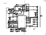
Page 20: ...CDP SP55 19 19 5 6 SCHEMATIC DIAGRAM MAIN SECTION See page 21 for IC Block Diagrams ...
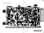
Page 60: ...ST SP55 6 6 3 3 SCHEMATIC DIAGRAM MAIN SECTION Page 8 Page 8 Page 8 PIN FUNCTION ...
Page 62: ...ST SP55 8 8 3 5 SCHEMATIC DIAGRAM PANEL SECTION Page 6 Page 6 Page 6 LCD BACK LIGHT ...
Page 102: ...8 MEMO ...
Page 105: ...TA SP55 11 11 4 3 SCHEMATIC DIAGRAM MAIN SECTION ...
Page 107: ...TA SP55 13 13 4 5 SCHEMATIC DIAGRAM PANEL SECTION ...
Page 133: ...CDP SP55 19 19 5 6 SCHEMATIC DIAGRAM MAIN SECTION See page 21 for IC Block Diagrams ...
Page 146: ...ST SP55 6 6 3 3 SCHEMATIC DIAGRAM MAIN SECTION Page 8 Page 8 Page 8 PIN FUNCTION ...
Page 148: ...ST SP55 8 8 3 5 SCHEMATIC DIAGRAM PANEL SECTION Page 6 Page 6 Page 6 LCD BACK LIGHT ...

