32
7.3.3 Operational Description
(1) Memory Stick Bock Configuration
The memory stick block consists of a CPU (IC101) with the built-in ARM 7 cores + MS I/F, digital signal
processing IC (IC301), magic gate IC (IC401), audio path control IC (IC601), A/D and D/A converter (IC501),
digital audio I/F (IC801), headphone amplifier (IC701), S-RAM (IC201), CMOS regulator (IC901, IC902, IC903,
IC904), SIM I/F (IC205), optical connector, remote control jack, and 64M memory stick.
(2) Audio Compression and Expansion Section
The audio data are compressed and expanded in the digital signal processing IC (IC301) to support the SDMI
(Water Mark compatible). For this purpose, the ATRAC3 system is used, and the compressed data are encrypted
in the magic gate IC (IC401), and stored in the memory stick. Also, the expanded data are D/A-converted, and its
low frequency components are amplified in the headphone amplifier (IC701) via audio path control IC (IC601),
then outputted to the headphone.
(3) Magic Gate Section
The memory stick recognition is made between magic gage IC (IC401) and magic gate IC in the memory stick via
CPU so as to check the memory stick for magic gate compatibility.
Further, at the recording, music data compressed in the digital signal processing IC (IC301) are encrypted and
stored in the memory stick.
Also, at the playing, the encrypted data in the memory stick are decrypted and led to the digital signal processing
IC (IC301).
(4) Audio Path Control Section
The output paths of received audio, played back audio, terminating tone and key tone are switched over to the
receiver, headphone, or earphone, and audio signals are mixed and the volume is controlled, then the signals are
led to the headphone amplifier.
(5) Digital Recording Section
Optical digital audio signals entered from optical connector are synchronized in the digital audio interface (IC801)
and demodulated into normal format, and led to the digital signal processing IC (IC301) and compressed there.
Then, they are encrypted in the magic gate IC (IC401) and stored in the memory stick.
(6) Analog Recording Section
Analog audio signals entered from optical connector are A/D-converted and led to the digital signal processing IC
(IC301) and compressed there, and then they are encrypted in the magic gate IC (IC401) and stored in the
memory stick.
(7) SIM Interface Section
This device is a SIM interface IC (IC205) with the built-in charge pump so as to support both 3V and 5V SIMs.
(8) Remote Control Section
The remote controller is equipped with the TEL key for originating a call and answering a terminating call, and the
microphone for the talk through earphone and the headphone output line.
The headphone output line is provided with a
φ
3.5 stereo mini pin jack, and commercial headphones can also be
used.
Summary of Contents for CMD-MZ5
Page 12: ...12 4 2 The Basic Features of the CMD MZ5 ...
Page 13: ...13 ...
Page 14: ...14 4 3 Icon Glossary ...
Page 15: ...15 4 4 Menu Overview ...
Page 16: ...16 ...
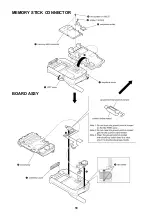
Page 18: ...18 MEMORY STICK CONNECTOR BOARD ASSY ...
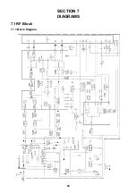
Page 24: ...24 SECTION 7 DIAGRAMS 7 1 RF Block 7 1 1 Block Diagram ...
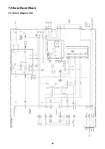
Page 27: ...27 7 2 Base Band Block 7 2 1 Block Diagram 1 2 ...
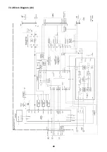
Page 28: ...28 7 2 2 Block Diagram 2 2 ...
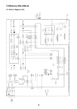
Page 30: ...30 7 3 Memory Stick Block 7 3 1 Block Diagram 1 2 ...
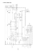
Page 31: ...31 7 3 2 Block Diagram 2 2 ...

