background image

45

 GB

Troubleshooting

Oth

e

rs

This section describes how to solve the problems, how to replace a lamp and 
air filter, etc.

Troubleshooting

If the projector appears to be operating erratically, try to diagnose and correct 
the problem using the following instructions. If the problem persists, consult 
with qualified Sony personnel.

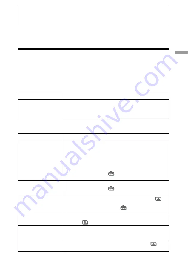
Power

Picture

Others

Symptom

Cause and Remedy

The power is not turned on.

c

Wait for about one minute before turning on the power. (

1

 page 

25)

c

Close the lamp cover securely. (

1

 page 48)

c

Close the air filter cover securely. (

1

 page 49)

Symptom

Cause and Remedy

No picture.

c

Check that the proper connections have been made. (

1

 page 

13)

c

Select the input source correctly using the INPUT button. (

1


page 24)

c

Set the computer signal to output from an external monitor.

c

Set the computer signal to output only to an external monitor.

c

Select “Computer,” “Component” or “Video GBR” for “Input-A 
Signal Sel.” in the Setup 

 menu according to the input 

signal. (

1

 page 42)

The picture from the 
INPUT A connector is 
colored strange.

c

Select “Computer,” “Component” or “Video GBR” for “Input-A 
Signal Sel.” in the Setup 

 menu according to the input 

signal. (

1

 page 42)

The picture from the 
VIDEO or S VIDEO 
INPUT connector is 
colored strange.

c

Adjust the picture in the “Adjust Picture” of the Picture 


menu (

1

 page 37)

c

Set “Color System” in the Setup 

 menu to match the color 

system being input. (

1

 page 42)

The picture is too dark.

c

Adjust the contrast or brightness in the “Adjust Picture” of the 
Picture 

 menu properly. (

1

 page 37)

The picture is not clear.

c

Adjust the focus with the focus ring. (

1

 page 25)

c

Condensation has occurred on the lens. Leave the projector for 
about two hours with the power on.

The picture flickers.

c

Adjust “Dot Phase” for “Adjust Signal” in the signal 

 menu 

properly. (

1

 page 39)

Summary of Contents for Cineza VPL-HS60

Page 1: ... 2004 Sony Corporation 2 188 141 E2 1 Video Projector Operating Instructions VPL HS50 ...

Page 2: ...uctions may cause harmful interference to radio communications However there is no guarantee that interference will not occur in a particular installation If this equipment does cause harmful interference to radio or television reception which can be determined by turning the equipment off and on the user is encouraged to try to correct the interference by one or more of the following measures Reo...

Page 3: ... klanten in Nederland Gooi de batterij niet weg maar lever deze in als klein chemisch afval KCA The socket outlet should be installed near the equipment and be easily accessible CAUTION RISK OF EXPLOSION IF BATTERY IS REPLACED BY AN INCORRECT TYPE DISPOSED OF USED BATTERIES ACCORDING TO THE LOCAL RULES ...

Page 4: ...GB 4 ...

Page 5: ...er 25 Selecting the Wide Screen Mode 26 Selecting the Picture Viewing Mode 29 Adjusting the Picture Quality 30 Adjusting the Picture Using Real Color Processing 32 Using the Menus Operation through the Menus 34 Picture Menu 37 Signal Menu 39 Function menu 40 Installation Menu 41 Setup Menu 42 Information Menu 43 About the Preset Memory No 43 Adjusting Picture Quality of a Signal from the Computer ...

Page 6: ...even if the unit itself has been turned off Do not look into the lens while the lamp is on Do not place your hand or objects near the ventilation holes The air coming out is hot On preventing internal heat build up After you turn off the power with the I 1 on standby switch do not disconnect the unit from the wall outlet while the cooling fan is still running Caution The projector is equipped with...

Page 7: ...to make sure it contains the following items Inserting the batteries into the remote control Connections and Preparations Remote control 1 Size AA R6 batteries 2 Air filter for replacement 1 AC power cord 1 Operating Instructions this manual 1 Insert the batteries E side first as shown in the illustration Inserting them forcibly or with the polarities reversed may cause a short circuit and may gen...

Page 8: ...you to choose a variety of installation locations for your projector You can enjoy home entertainment with this projector in the following situations Enjoying home theater Watching sports etc with your company Enjoying video games on a large screen Viewing images shot by a digital video camera on a large screen ...

Page 9: ...caused Very dusty and extremely smoky Make a special attention to the following while using the projector Do not block the ventilation holes Tip For details on the location of the ventilation holes intake or exhaust see Location of Controls on pages 60 to 62 When installing the unit at altitudes When using the projector at an altitude of 1 500 m or higher set High Altitude Mode in the Installation...

Page 10: ...nce between the center of the screen and the center of the projector s lens when using the maximum vertical lens shift feature d Horizontal distance between the center of the screen and the center of the projector s lens when using the maximum horizontal lens shift feature e Maximum vertical distance between the center of the screen and the center of the projector s lens when using both the vertic...

Page 11: ...6 1 4 b maximum 1790 70 1 2 2710 106 3 4 3630 143 4540 178 7 8 5460 215 6830 269 8210 323 3 8 9120 359 1 8 c 498 19 5 8 747 29 1 2 996 39 1 4 1245 49 1 8 1494 58 7 8 1868 73 5 8 2241 88 1 4 2491 98 1 8 d 443 17 1 2 664 26 1 4 886 35 1107 43 5 8 1328 52 3 8 1660 65 3 8 1992 78 1 2 2214 87 1 4 e 249 9 7 8 374 14 3 4 498 19 5 8 623 24 5 8 747 29 1 2 934 36 7 8 1121 44 1 4 1245 49 1 8 Screen size inch...

Page 12: ...To project an image connect video equipment to the projector 1 page 13 When using a screen with an uneven surface stripes pattern may rarely appear on the screen depending on the distance between the screen and the projector or the zooming magnifications This is not a malfunction of the projector For installation of the projector on a ceiling see Ceiling Installation 1 page 57 Note Screen Top view...

Page 13: ... digital tuner equipped with component video connectors Tip To connect the projector to a DVD player recorder digital tuner etc which is not equipped with component video connectors use the S video cable to connect to the S video output of the DVD player recorder digital tuner etc If the connected equipment is not equipped with the S video output connector use the video cable to connect to the vid...

Page 14: ... recorder equipped with HDMI output to the HDMI input of the projector Y PB CB PR CR VIDEO HDMI INPUT HDMI cable not supplied Video signal flow Rear of the projector DVD player recorder etc with the HDMI output to HDMI output AV amplifier Speakers HDMI HDMI logo and High Definition Multimedia Interface are trademarks or registered trademarks of HDMI Licensing LLC ...

Page 15: ...ou do not know to which connector you should connect the cable S VIDEO S video connector or VIDEO video connector connect it to S VIDEO to enjoy better picture quality If the equipment to be connected has no S video connector connect the cable to the video output Connecting to Video Equipment S VIDEO INPUT A PR CR VIDEO INPUT S video or video cable not supplied Video signal flow Rear of the projec...

Page 16: ... to both your computer s display and an external monitor the picture of the external monitor may not appear properly Set your computer to output the signal to only the external monitor For details refer to the computer s operating instructions supplied with your computer Connecting to a Computer Note S VIDEO INPUT A PR CR VIDEO INPUT HD D sub 15 pin cable not supplied Video signal flow Rear of the...

Page 17: ...same as those on the remote control Depending on the installation location of the projector you may not control it with the remote control In this case point the remote control to the screen instead of the projector 1 Plug the AC power cord into a wall outlet The ON STANDBY indicator lights in red and the projector goes into standby mode Note INPUT LIGHT STANDARD CINEMA DYNAMIC USER 2 PICTURE MODE...

Page 18: ...f the connected equipment 4 Press INPUT to project the picture on the screen Each time you press the button the input indication changes 1 page 24 Tip When Auto Input Search is set to On in the Function menu the channel of the signal input is automatically displayed 5 Move both LENS SHIFT dials to adjust the picture position ON STANDBY Lights in green Video INPUT LENS SHIFT To adjust the vertical ...

Page 19: ...lens To adjust the vertical position Turn the LENS SHIFT dial up or down The picture moves up or down by a maximum of the screen size from the center of the lens Top view Picture position when moving the picture to the left at maximum Picture position when moving the picture to the right at maximum 1 2H 1H 1 2H Side view Picture position when moving the picture upward at maximum Picture position w...

Page 20: ... the picture vertically by a maximum of half of the screen size 6 Adjust the picture size using the zoom ring 7 Adjust the focus using the focus ring To adjust the tilt of the installation surface If the projector is installed on an uneven surface use the adjusters to keep the projector level Note Zoom ring Focus ring Adjusters Turn to adjust ...

Page 21: ...TER buttons on the remote control 1 Plug the AC power cord into a wall outlet The ON STANDBY indicator lights in red and the projector goes into standby mode 2 Press the I 1 on standby switch to turn on the projector The ON STANDBY indicator lights in green 3 Press MENU The menu appears INPUT LIGHT STANDARD CINEMA DYNAMIC USER 2 PICTURE MODE USER 3 USER 1 ADJ PIC MENU APA RCP RESET WIDE MODE ENTER...

Page 22: ...to select a language and press ENTER The menu changes to the selected language To clear the menu Press MENU ENTER Sel Set Back Exit Picture Signal Function Setup Installation Information Status On Language English Input A Signal Sel Computer Color System Auto or ENTER Sel Set Exit Picture Signal Function Setup Installation Information Status On Language English Input A Signal Sel Center Color Syst...

Page 23: ... cord into a wall outlet The ON STANDBY indicator lights in red and the projector goes into standby mode 2 Press the I 1 on standby switch to turn on the projector The ON STANDBY indicator lights in green 3 Turn on the equipment connected to the projector Refer to the operating instructions of the connected equipment Projecting INPUT LIGHT STANDARD CINEMA DYNAMIC USER 2 PICTURE MODE USER 3 USER 1 ...

Page 24: ...an appropriate signal with Input A Signal Sel 1 page 42 Tip When Auto Input Search is set to On in the Function menu the channel of the input signal is automatically displayed 5 Turn the zoom ring to adjust the size of the picture Video INPUT To view the picture from Press INPUT to display Video equipment connected to the VIDEO INPUT connector Video Video equipment connected to S VIDEO INPUT conne...

Page 25: ...and the fan continues to run to reduce the internal heat First the ON STANDBY indicator flashes quickly during which you will not be able to light up the ON STANDBY indicator with the I 1 switch 3 Unplug the AC power cord from the wall outlet after the fan stops running and the ON STANDBY indicator lights in red You can turn off the projector by holding the I 1 on standby switch for about one seco...

Page 26: ...button you can select the Wide Mode setting Full A picture squeezed to 4 3 is displayed with the correct aspect ratio A 4 3 picture is enlarged horizontally to fit the 16 9 screen Tip Squeezed An original 16 9 aspect ratio picture is recorded horizontally compressed to a 4 3 picture INPUT LIGHT STANDARD CINEMA DYNAMIC USER 2 PICTURE MODE USER 3 USER 1 ADJ PIC MENU APA RCP RESET WIDE MODE ENTER REA...

Page 27: ...m A normal 4 3 aspect ratio picture is enlarged vertically and horizontally in the same ratio to fill the 16 9 screen This mode is ideal for viewing a wide format movie Subtitle The subtitle area is compressed and displayed in the lower part of the screen Use this mode to view a movie with subtitles You can adjust the vertical position of the picture with V Position in the Signal menu only when Zo...

Page 28: ...nging the aspect ratio of the original picture will provide a different look from that of the original image Note that if the projector is used for profit or for public viewing modifying the original picture by switching to the wide mode may constitute an infringement of the rights of authors or producers which are legally protected ...

Page 29: ...lm like picture in dark environment USER 1 2 and 3 You can adjust the quality of the picture to suit your taste and store the settings into the selected memory of the projector Press one of the USER 1 2 and 3 buttons then adjust the picture by using the buttons on the remote control or the menus 1 pages 30 and 37 The settings are stored and you can view the picture with the adjusted picture qualit...

Page 30: ...are displayed in sequence Some of the above adjustment windows will not be displayed depending on the input signal For details see Input Signals and Adjustable setting Items 1 page 53 INPUT LIGHT STANDARD CINEMA DYNAMIC USER 2 PICTURE MODE USER 3 USER 1 ADJ PIC MENU APA RCP RESET WIDE MODE ENTER CONTRAST BRIGHT REAL COLOR PROCESSING ADJ PIC button CONTRAST button BRIGHT button Contrast t Brightnes...

Page 31: ...e the setting or adjustment on an item When changing the adjustment level To increase the value press M or To decrease the value press m or When changing the setting Press M or m to change the setting To adjust contrast and brightness Press CONTRAST on the remote control to adjust the contrast Press BRIGHT on the remote control to adjust the brightness Contrast ...

Page 32: ...g window appears 3 Select the target color you want to adjust Repeat steps 1 and 2 described below to specify the target color 1 Press M or m to select Color Select then press or to select the color you want to adjust among Red Magenta Blue Cyan Green and Yellow Only the portions that correspond to the specified color will be colored and the other portions will be displayed in black and white The ...

Page 33: ...ching the projected picture The picture is returned to normal color during adjustment 5 After the adjustment is complete press RCP The RCP window disappears and the normal picture is restored The adjusted data will be stored in a memory selected in step 2 and will be recalled later Tip There are some limitations on selection of position and range Sel Set Exit RCP Real Color Processing Color Select...

Page 34: ...enu with no main menu or in the next menu window If you select an item name followed by an arrow B the next menu window with setting items appears To change the on screen menu language see Selecting the Menu Language 1 page 21 1 Press MENU The menu window appears Using the Menus INPUT LIGHT STANDARD CINEMA DYNAMIC USER 2 PICTURE MODE USER 3 USER 1 ADJ PIC MENU APA RCP RESET WIDE MODE ENTER REAL CO...

Page 35: ...ms are displayed in a pop up menu in a setting menu in an adjustment menu or in the next menu window Picture Signal Function Setup Installation Information Status Language Input A Signal Sel Component Color System Auto English On Sel Set Back Exit ENTER Sel Set Exit Picture Signal Function Setup Installation Information Status On Language English Input A Signal Sel Center Color System White or Pop...

Page 36: ...appears on the screen and the setting is reset to its factory preset value Items that can be reset are Contrast Brightness Color Hue Sharpness and Color Temp in Adjust Picture and RCP of the Picture menu Dot Phase H Size and Shift in Adjust Signal of the Signal menu V Keystone of the Installation menu Items that cannot be adjusted Adjustable items are limited depending on the input signals The ite...

Page 37: ...p You can also adjust the picture quality in Dynamic Standard or Cinema and store the settings To reset to the factory setting press RESET Adjust Picture Contrast The higher the setting the greater the contrast The lower the setting the lower the contrast Brightness The higher the setting the brighter the picture The lower the setting the darker the picture Color The higher the setting the greater...

Page 38: ...select this option Reproduces the 2 3 Pull Down film sources with smooth picture movement When the video signal with a format other than the 2 3 Pull Down is input Progressive is automatically selected Cinema Black Pro Advanced Iris Switches the iris function during projection Off Normal contrast On Enhances the black by emphasizing the contrast Auto Automatically switches to an optimum iris accor...

Page 39: ...ect Normal The 4 3 aspect ratio picture is displayed to fill the vertical screen size Wide Zoom The 4 3 aspect ratio picture is enlarged and the upper and lower portions are compressed to fit the 16 9 screen Zoom The 4 3 aspect ratio picture is enlarged vertically and horizontally at the equal ratio to fill the 16 9 screen Subtitle The subtitle area is compressed and displayed at the lower part of...

Page 40: ...en the INPUT button is pressed Then the detected input channel is automatically displayed Set to Off when you want to select the channel with no input signal or you want to switch the channel manually Standby Mode When set to Low the power consumption in standby mode is lowered Power Saving When set to On the POWER SAVING indicator lights The projector goes into power saving mode if no signal is i...

Page 41: ...djustment Image Flip Flips the picture on the screen horizontally and or vertically Off The picture does not flip HV Flips the picture horizontally and vertically H Flips the picture horizontally V Flips the picture vertically Background Selects the background color of the screen when no signal is input You can select Black or Blue Illumination Turns on the illumination on the top panel of the pro...

Page 42: ...A with the INPUT button Auto Selects the input signal type automatically Computer Inputs the signal from a computer Component Inputs the component signal from a DVD player recorder digital tuner etc Video GBR Inputs the signal from a TV game or HDTV broadcast Note When the input signal is not displayed correctly with this item set to Auto select the item according to the input signal Color System ...

Page 43: ...nput signal When an unpreset signal is input for the first time a memory number is displayed as 0 When you adjust the data of the signal in the Signal menu it will be registered to the projector If more than 20 user memories are registered the newest memory always overwrites the oldest one See the chart on page 55 to find if the signal is registered to the preset memory When the aspect ratio of in...

Page 44: ...the suitable picture To restore the original screen press the APA button again during the adjustment When a signal of which the timing is the same as the Memory No 37 or the Memory No 55 signal refer to the Preset Signals chart is input if the polarity of the synchronized signal is different the input signal may be misjudged and the image may not appear properly incorrect aspect ratio or lack of a...

Page 45: ...et the computer signal to output only to an external monitor c Select Computer Component or Video GBR for Input A Signal Sel in the Setup menu according to the input signal 1 page 42 The picture from the INPUT A connector is colored strange c Select Computer Component or Video GBR for Input A Signal Sel in the Setup menu according to the input signal 1 page 42 The picture from the VIDEO or S VIDEO...

Page 46: ...urely 1 pages 48 and 49 LAMP COVER lights up c The lamp has reached the end of its life Replace the lamp 1 page 48 c The lamp becomes a high temperature Wait until the lamp cools and then turn on the power again 1 page 25 TEMP FAN flashes c The fan is broken Consult with qualified Sony personnel TEMP FAN lights up c The internal temperature is unusually high Check to see if nothing is blocking the...

Page 47: ...omputer when RGB signal is input from the computer 1 page 42 Please replace the LAMP c It is time to replace the lamp Replace the lamp 1 page 48 Please replace the filter c It is time to replace the air filter Replace the air filter 1 page 49 High temp Probably use in high altitude Switch to high altitude mode on Yes O No o c When using the projector at an altitude of 1 500 m or higher select Yes ...

Page 48: ... to cool When removing the lamp unit make sure it remains horizontal then pull straight up Do not tilt the lamp unit If you pull out the lamp unit while tilted and if the lamp breaks the pieces may scatter causing injury 1 Turn off the projector and unplug the AC power cord 2 Place a protective sheet cloth beneath the projector Turn the projector over so you can see its underside Be sure that the ...

Page 49: ...amp cover is securely closed Replacing the Air Filter The air filter should be replaced periodically When Please replace the filter appears on the screen replace the air filter immediately Replacing the air filter is very important to maintain the high efficiency of the projector and to prevent a malfunction When the replacement message appears on the screen replace the air filter without delay It...

Page 50: ...GB 50 Replacing the Air Filter 4 Insert the new air filter into the projector 5 Replace the filter cover The projector will not turn on unless the filter cover is securely closed Note ...

Page 51: ...erminated burst 0 3 Vp p 2 dB PAL 75 ohms terminated Y PB CB PR CR Component phono type G with Sync Y 1 Vp p 2dB sync negative 75 ohms terminated B CB PB 0 7 Vp p 2dB positive 75 ohms terminated R CR PR 0 7 Vp p 2 dB positive 75 ohms terminated HDMI Digital RGB Y CB PB CR PR INPUT A HD D sub 15 pins Analog RGB component R CR PR 0 7 Vp p 2 dB 75 ohms terminated G 0 7 Vp p 2 dB 75 ohms terminated G ...

Page 52: ...sign and specifications are subject to change without notice Safe regulations UL60950 CSA No 950 FCC class B IC class B EN60950 NEMKO CE C Tick Optional accessories Projector Lamp LMP H130 for replacement Air filter PK HS10FL for replacement Projector Suspension Support PSS 610 ...

Page 53: ...ope UK Ireland Australia New Zealand Japan Plug type VM0233 290B YP 12A COX 07 YP332 Female end VM0089 386A YC 13B COX 02 VM0310B YC 13 Cord type SJT SJT H05VV F H05VV F N13237 CO 228 VCTF Rated Voltage Current 10A 125V 10A 125V 10A 250V 10A 250V 10A 250V 7A 125V Safety approval UL CSA UL CSA VDE VDE VDE DENANHO Input Signals and Adjustable setting Items Item Input signal Video or S video Y C Comp...

Page 54: ...only Cinema Black Pro Advanced Iris z z z z z Lamp Control z z z z z Item Input signal Video or S video Y C Component Video GBR Computer HDMI Dot Phase z H size z Shift z preset memory numbers 5 6 7 8 9 10 11 only z preset memory numbers 5 6 7 8 9 10 11 only z z Wide Mode z z preset memory numbers 3 4 5 6 only z preset memory numbers 3 4 5 6 only z preset memory numbers 3 4 5 6 only Item Input sig...

Page 55: ...onG Y z 8 1080 50i 1080 50i 28 130 50 000 SonG Y z 9 1080 24PsF 1080 48i 27 000 48 000 SonG Y z 10 720 60p 720 60p 45 000 60 000 SonG Y z 11 720 50p 720 50p 37 500 50 000 SonG Y z 21 640 350 VGA 1 VGA350 31 469 70 086 H pos V neg 800 22 VESA 85 VGA350 37 861 85 080 H pos V neg 832 23 640 400 NEC PC98 24 823 56 416 H neg V neg 848 24 VGA 2 TEXT VESA70 31 469 70 086 H neg V pos 800 25 VESA 85 VGA400...

Page 56: ...os 1040 34 VESA 75 IBM M5 46 875 75 000 H pos V pos 1056 35 VESA 85 53 674 85 061 H pos V pos 1048 36 832 624 Mac 16 49 724 74 550 H neg V neg 1152 37 1024 768 VESA 60 48 363 60 004 H neg V neg 1344 38 VESA 70 56 476 70 069 H neg V neg 1328 39 VESA 75 60 023 75 029 H pos V pos 1312 55 1280 768 WXGA 60 47 776 59 870 H neg V pos 1664 56 1280 720 WXGA 60 44 772 59 855 H neg V pos 1664 Note Memory No ...

Page 57: ...81 5 8 5510 217 6120 241 Maximum Distance 1910 75 1 4 2830 111 1 2 3750 147 3 4 4660 183 1 2 5580 219 3 4 6950 273 3 4 8330 328 9240 363 7 8 x Minimum Distance 174 6 7 8 299 11 7 8 423 16 3 4 548 21 5 8 672 26 1 2 859 33 7 8 1046 41 1 4 1170 46 1 8 Maximum Distance b 423 b 16 3 4 b 672 b 26 1 2 b 921 b 36 3 8 b 1170 b 46 1 8 b 1419 b 55 7 8 b 1793 b 70 5 8 b 2166 b 85 3 8 b 2416 b 95 1 4 b 150 175...

Page 58: ...screen Screen Size inches 40 60 80 100 120 150 180 200 a Minimum Distance 1560 61 1 2 2300 90 5 8 3040 119 3 4 3780 148 7 8 4510 177 5 8 5620 221 3 8 6730 265 7470 294 1 4 Maximum Distance 2320 91 3 8 3450 135 7 8 4570 180 5690 224 1 8 6810 268 1 4 8490 334 3 8 10170 400 1 2 11290 444 5 8 x Minimum Distance 230 9 1 8 382 15 1 8 535 21 1 8 687 27 1 8 839 33 1 8 1068 42 1 8 1297 51 1 8 1449 57 1 8 M...

Page 59: ...Center of the supporting pole Center of the lens Distance between the ceiling and the surface of the mount bracket Using adjustment pipe b 150 175 200 mm 6 7 7 7 8 inches Using adjustment pipe c 250 275 300 mm 9 7 8 10 7 8 11 7 8 inches 224 5 8 7 8 216 5 8 5 8 152 5 6 1 8 135 5 5 3 8 13 17 32 Center of the lens Front of the cabinet ...

Page 60: ... FAN POWER SAVING ON STANDBY MENU I 1 on standby switch 1 page 18 INPUT button 1 page 24 MENU button 1 page 21 M m arrow button 1 page 22 LAMP COVER indicator 1 page 46 TEMP FAN Indicator 1 page 46 POWER SAVING indicator 1 page 40 ON STANDBY indicator 1 page 17 Zoom ring 1 page 20 Focus ring 1 page 20 Ventilation holes exhaust 1 page 9 LENS SHIFT dials 1 page 18 Remote control detector 1 page 17 ...

Page 61: ... page 49 Air fliter cover 1 page 49 Ventilation holes intake 1 page 9 TRIGGER jack minijack Outputs a 12 V signal when the power is on AC IN socket HDMI connector 1 page 14 Y PB CB PR CR phono type 1 page 13 INPUT A connector 1 page 16 S VIDEO INPUT connector mini DIN 4 pin VIDEO INPUT jack phono type 1 page 15 ...

Page 62: ...GB 62 Location of Controls Bottom Adjusters 1 page 20 Lamp cover 1 page 48 Ventilation holes intake 1 page 9 Projector suspension support attachment holes 1 page 58 ...

Page 63: ...JHS50 PROJECTOR Infrared transmitter I 1 on standby switch 1 page 18 MENU button 1 page 21 M m arrow ENTER buttons 1 page 22 RESET button 1 page 36 RCP button 1 page 32 CONTRAST button 1 page 31 BRIGHT button 1 page 31 INPUT button 1 page 24 LIGHT button Illuminates the buttons on the remote control PICTURE MODE buttons 1 page 29 ADJ PIC button 1 page 30 APA button 1 page 44 WIDE MODE button 1 pag...

Page 64: ...eo Equipment 15 Contrast 37 D DDE 38 Dot Phase 39 F fH 43 Function menu 40 fV 43 G Gamma Correction 38 H H Size 39 HDMI output 14 High Altitude Mode 41 Hue 37 I Illumination 41 Image Flip 41 Information menu 43 Input A Signal Sel 42 Installation menu 41 Installing the Projector and a Screen 10 57 L Lamp Timer 43 Language 42 Lens shift feature 18 Location of Controls Bottom 62 Front 60 Rear 61 M Me...

Page 65: ...8 Reset resettable items 36 resetting the items 36 S Selecting the menu language 21 Setup menu 42 Sharpness 37 Shift 39 Signal menu 39 Smart APA 40 Standby Mode 40 Status 42 Supplied accessories 7 T Title Area 39 Troubleshooting 45 V V Keystone 41 V Position 39 Ventilation holes 9 W Warning Indicators 46 WIDE MODE 26 Wide Mode 26 39 ...

Page 66: ...GB 66 Index ...

Page 67: ...67GB Index Other ...

Page 68: ...ower consumption in standby is 0 5 W Lead free solder is used for soldering Halogenated flame retardants are not used in cabinets and printed wiring boards Polystyrene foam for the packaging cushions is not used in packaging 100 recycled paper is used for the carton ...

Reviews: