3
TABLE OF CONTENTS
1. SERVICING NOTES
......................................................... 4
2. GENERAL
............................................................................ 5
3. DISASSEMBLY
3-1. Cabinet Top Assy ................................................................ 7
3-2. Cabinet Front Assy, Cabinet Rear Assy .............................. 7
3-3. Wires ................................................................................... 8
3-4. MD Block ............................................................................ 8
3-5. Cassette Door Assy ............................................................. 9
3-6. LCD Board, Control (4) Board ........................................... 9
3-7. Main Board ....................................................................... 10
3-8. Tuner Board ....................................................................... 10
3-9. Power Board ...................................................................... 11
3-10. CD Lid ............................................................................... 11
3-11. CD Block Assy .................................................................. 12
3-12. Optical Pick-up ................................................................. 12
3-13. R/P Head (HRP301), TC Board ........................................ 13
3-14. Motor Assy (M801), Main Belt (B), Sub Belt (B) ............ 13
4. MECHANICAL ADJUSTMENTS
............................... 14
5. ELECTRICAL ADJUSTMENTS
Tape Section .......................................................................... 14
Tuner Section ......................................................................... 15
CD Section ............................................................................ 16
6. DIAGRAMS
6-1. IC Pin Descriptions ........................................................... 17
6-2. Circuit Boards Location .................................................... 19
6-3. Block Diagram – CD Section – ......................................... 20
6-4. Block Diagram – Main Section – ...................................... 21
6-5. Printed Wiring Board – CD Section – ............................... 22
6-6. Schematic Diagram – CD Section – .................................. 24
6-7. Printed Wiring Board – Tuner Section – ........................... 25
6-8. Schematic Diagram – Tuner Section – .............................. 26
6-9. Printed Wiring Boards – Main Section – .......................... 27
6-10. Schematic Diagram – Main Section (1/2) – ...................... 28
6-11. Schematic Diagram – Main Section (2/2) – ...................... 29
6-12. Printed Wiring Board – TC Section – ............................... 30
6-13. Schematic Diagram – TC Section – .................................. 31
6-14. Printed Wiring Boards – Control Section – ....................... 32
6-15. Schematic Diagram – Control Section – ........................... 33
6-16. Printed Wiring Boards – Display Section – ...................... 34
6-17. Schematic Diagram – Display Section – ........................... 35
6-18. Printed Wiring Boards – Power Supply Section – ............ 36
6-19. Schematic Diagram – Power Supply Section – ................. 37
6-20. IC Block Diagrams ............................................................ 38
7. EXPLODED VIEWS
7-1. Main Section ..................................................................... 40
7-2. Cabinet Front Section ........................................................ 41
7-3. Cabinet Top Section .......................................................... 42
7-4. Cabinet Rear Section ......................................................... 43
7-5. Tape Mechanism Section .................................................. 44
7-6. CD Mechanism Section .................................................... 45
8. ELECTRICAL PARTS LIST
......................................... 46
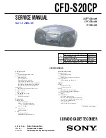
CFD-S20CP
Summary of Contents for CFD-S20CP - Cd Radio Cassette-corder
Page 56: ...56 CFD S20CP MEMO ...


