background image

CDX-GT48UM/GT480U/GT480US/GT484US

CDX-GT48UM/GT480U/GT480US/GT484US

15

15

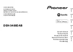
4-1.  BLOCK  DIAGRAM  – MAIN Section –

SECTION  4

DIAGRAMS

20
22

11
12
28

8

17
18

3

25

7

19
27
13
24

4

AU_LCH
AU_RCH

TXD(MC-BUS)
RXD(MC-BUS)
WAKE UP
Z_MUTE
CD_ON
CDM_ON

SYS_RST
EJECT_OK
VBUS ON

A_ATT
BU CHECK
MECHA 8.5V
A+3.3V
BU_+3.3V
DR_+6V

R-CH

R-CH

R-CH

R-CH

R-CH

AUDIO +8.5V

BU_+3.3V

SERVO+3.3V

R-CH

7 AUX-L
9 AUX-R

BU+3.3V

MC RX

59

MC TX

60

WAKE UP

58

Z-MUTE

62

CD_ON

27

CDM_ON

28

RESET

54

SYSRST

26

V-BUS ON

BU +3.3V

70

CLK IN

61

MD2

51

MD0

53

FLASH EN1

78

VOUT

1

VIN 2

15

D701

4 FMIN1
3 FMIN2

3 TU-L

8 AUX GND

ELECTRONIC VOLUME

IC302

J1

(ANTENNA)

PHASE LOCKED LOOP

(PLL)

IC001

L6

FM MIX

L2

CN701

CD

MECHANISM

UNIT

(MG-101Y)

(1/2)

I2C BUS CONTROLLED

POWER AMP/MULTIPLE
VOLTAGE REGULATOR

IC301

SYSTEM CONTROL

IC401 (1/2)

RESET

IC403

CN802

4 TU-R

5 CD-L
6 CD-R

R-CH (FRONT)
R-CH (REAR)

BATT

R-CH

8
9

18

SCL

19

SDA

14

RSSI

37 VSM

16 XTAL1

15 XTAL2

LOUT

ROUT

J901
AUX

X1

4MHz

S401

RESET

5
3

OUT-FL+
OUT-FL–

9
7

OUT-RL+
OUT-RL–

27

R-CH

ANT-REM

35

VP

BATT

20

VP1

6

VP2

30

AUDIO+B

31
33

SERVO+3.3V

MECHA+6V

34

PANEL+B

34
32

OUT-FR

27

SACLK

28

SADA

29

SAOUT

OUT-RR

R-CH

31

R/S OUT-L

13

ZAPPIN1

16

ZAPPIN2

4 SCL

AUDIO +8.5V
SERVO+3.3V
MECHA+6V
PANEL+B

2 SDA

16 BEEP
22 STB
25 DIAG

7

10

12

11

16

1
9

2

4

3

6

37
38

SCL

SDA

I2C-SCK
I2C-SIO

I2C-SCK
I2C-SIO

I2C-SCK
I2C-SIO

I2C-SCK
I2C-SIO

23

I2C_SCK

72

SACLK

71

SAOUT

38

SAIN

22

I2C_SIO

31

ATT

47

EXATT_XEN

98

ZAPPIN

97

BEEP

68

AMPSTB

69

DIAG

83

BU CHECK

12 IN-FL

FL+
FL–

L

R

RL+
RL–

FR+
FR–
RR+
RR–

ANT-REM

BATT

ACC

35

OUT-FL

11 IN-RL

33

OUT-RL

MUTE

Q102

MUTE DRIVE

Q303,304

29

ACC IN

ACC DETECT

Q805

+3.3V REG

IC402

MUTE

Q103

29

AMP-REM

5

AMP-REM

1 AMRFIN

REAR/SUB

D306

D308

D309

FU601

37

BU+B

B.U+5V

FRONT

R-CH

L

J302

R

-1

-2

-3

-4

AUDIO

OUT

MUTE

Q104

BU+3.3V

BATT

2

3

BACK-UP CHECK

Q802,807,808,

D806,807

MECHA +6V

3.3V

6

UART_CLK

3

FLASH_W

7

CLK IN

2

RESET

RX

4

1

5

TX

CN401
FLASH

PROGRAMMING

BU +3.3V

B.U +5V

R-CH (REAR/SUB)

30

R/S OUT-R

CD MUTE

Q305

FLASH

PROGRAMMING

BUFFER

Q401,402

• Signal Path

• R-CH is omitted due to same as L-CH.

: AM

: CD

: FM

: AUX

Summary of Contents for CDX-GT480U

Page 1: ...quency 25 kHz Sensitivity 26 μV USB Player section Interface USB Full speed Maximum current 500 mA Power amplifier section Outputs Speaker outputs sure seal connectors Speaker impedance 4 8 ohms Maximum power output 52 W 4 at 4 ohms General Outputs Audio outputs terminal front sub rear switchable Power antenna aerial relay control terminal Power amplifier control terminal Inputs Remote controller ...

Page 2: ...asily damaged and should be handled with care NOTES ON LASER DIODE EMISSION CHECK The laser beam on this model is concentrated so as to be focused on the disc reflective surface by the objective lens in the optical pickup block Therefore when checking the laser diode emission observe from more than 30 cm away from the objective lens CAUTION Use of controls or adjustments or performance of procedur...

Page 3: ...is best to use only unleaded solder but unleaded solder may also be added to ordinary solder CD Playback You can play CD DA also containing CD TEXT and CD R CD RW MP3 WMA AAC files This compact disc player is classified as a CLASS 1 LASER product The CLASS 1 LASER PRODUCT label is located on the exterior This label is located on the bottom of the chassis 1 SERVICE NOTE 4 2 GENERAL Location of Cont...

Page 4: ...cannot be repaired NOTE FOR REPLACEMENT OF THE USB CONNECTOR CN902 To replace the USB connector requires alignment 1 Insert the USB connector into the front panel 2 Place the KEY board on the front panel and align the terminals of the USB connector with the holes in the KEY board 3 Solder the four terminals of the connector SERVO BOARD CN401 MAIN BOARD CN701 J 2502 076 1 KEY board front panel USB ...

Page 5: ...ote commander RESET button located behind the front panel page 4 0 ZAP button page 9 To enter ZAPPIN mode 1 BTM button page 9 To start the BTM function press and hold 2 Frequency select switch located on the bottom of the unit See Frequency select switch in the supplied installation connections manual 3 Number buttons CD USB ALBM during MP3 WMA AAC playback To skip albums press skip albums continu...

Page 6: ...t in amplifiers to the speaker terminals may damage the unit To avoid a malfunction do not use the built in speaker leads installed in your car if the unit shares a common negative lead for the right and left speakers Do not connect the unit s speaker leads to each other Note on connection If speaker and amplifier are not connected correctly FAILURE appears in the display In this case make sure the ...

Page 7: ...ails consult your dealer A power antenna aerial without a relay box cannot be used with this unit Memory hold connection When the yellow power supply lead is connected power will always be supplied to the memory circuit even when the ignition switch is turned off Notes on speaker connection Before connecting the speakers turn the unit off Use speakers with an impedance of 4 to 8 ohms and with adeq...

Page 8: ...SUB PANEL ASSY Page 9 3 2 CD MECHANISM BLOCK Page 9 SET 3 3 MAIN BOARD Page 10 3 5 CHASSIS T SUB ASSY Page 11 3 6 ROLLER ARM ASSY Page 11 3 7 CHASSIS OP ASSY Page 12 3 8 CHUCKING ARM SUB ASSY Page 12 3 9 SLED MOTOR ASSY Page 13 3 10 OPTICAL PICK UP SECTION Page 14 3 11 OPTICAL PICK UP Page 14 3 4 SERVO BOARD Page 10 ...

Page 9: ... disassembly procedure in the numerical order shown below 3 1 SUB PANEL ASSY 3 2 CD MECHANISM BLOCK two claws two claws sub panel assy two screws PTT 2 6 6 CN701 CN501 3P screw PTT 2 6 6 screw PTT 2 6 6 two screws PTT 2 6 4 bracket CD CD mechanism block ...

Page 10: ...ews PTT 2 6 8 three screws BTT screw PTT 2 6 10 heat sink two screws P 2 6 8 screw P 2 6 10 two screws PTT 2 6 10 SERVO board SERVO board toothed lock screw M 1 7 2 5 toothed lock screw M 1 7 2 5 Remove the eleven solders GRY YEL BLU ORG RED BLK RED WHT BLK RED WHT claw claw optical pick up 16 core CN101 ...

Page 11: ...M GT480U GT480US GT484US 11 3 5 CHASSIS T SUB ASSY 3 6 ROLLER ARM ASSY chassis T sub assy claw two precision screws P 1 7 2 2 two precision screws P 1 7 2 2 washer gear RA1 roller arm assy spring RAL spring RAR ...

Page 12: ...ASSY two coil springs damper natural coil spring damper green chassis OP assy tension spring KF gear LE1 lever D slider R chucking arm sub assy spring Note Have this portion receive the chassis Note Have this portion receive the chassis Note Be careful not to touch the turn table ...

Page 13: ... turn table three serration screws M 2 3 three serration screws M 2 3 Note Place the stand with care not to touch the turn table Note Never remove these parts since they were adjusted Note for Assembly Note Take care to prevent the chassis from being bent when tightening the three machine screws bearing R bearing F ...

Page 14: ...pick up section There is space at the end of the leaf spring sub guide to avoid contact with the slide pan tapping screw M 1 4 3 5 leaf spring sub guide leaf spring OP optical pick up lead screw assy Notes for Assembly Prevent the end of the leaf spring sub guide from being in contact with the OP slide base Prevent the end of the leaf spring sub guide from being in contact with the OP slide base ...

Page 15: ... J901 AUX X1 4MHz S401 RESET 5 3 OUT FL OUT FL 9 7 OUT RL OUT RL 27 R CH ANT REM 35 VP BATT 20 VP1 6 VP2 30 AUDIO B 31 33 SERVO 3 3V MECHA 6V 34 PANEL B 34 32 OUT FR 27 SACLK 28 SADA 29 SAOUT OUT RR R CH 31 R S OUT L 13 ZAPPIN1 16 ZAPPIN2 4 SCL AUDIO 8 5V SERVO 3 3V MECHA 6V PANEL B 2 SDA 16 BEEP 22 STB 25 DIAG 7 10 12 11 16 1 9 2 4 3 6 37 38 SCL SDA I2C SCK I2C SIO I2C SCK I2C SIO I2C SCK I2C SIO...

Page 16: ...NTROL SIGNAL RECEIVER IC902 Q907 LED DRIVER Q901 LCD BACK LIGHT DIMMER CONTROL Q902 LCD BACK LIGHT CONTROL LED907 911 913 915 922 924 925 930 931 LSW901 905 913 LED926 929 GT48UM LED928 932 935 GT480U GT480US GT484US RING ILLUMINATION LED901 LCD BACK LIGHT 3 USB POWER CONTROL SWITCH IC503 99 SYNC OUT 24 USB OVER 21 USB ON BATT 100 DD ON VIN VBUS 1 3 VOUT D505 L502 DC DC CONVERTER CONTROL IC502 CD ...

Page 17: ...pe Voltage variations may be noted due to normal production tolerances Circled numbers refer to waveforms Signal path J CD F FM f AM L AUX c USB Abbreviation MX Mexican model AR Argentina model For Printed Wiring Boards Note X Parts extracted from the component side Y parts extracted from the conductor side a Through hole Pattern from the side which enables seeing The other layers patterns are not...

Page 18: ...258 JW259 JW260 JW261 FB301 JW262 JW263 JW264 JW265 R101 JW266 JW267 R103 JW268 R104 JW269 R106 R107 JW270 JW271 JW272 R302 JW273 R303 R304 JW274 JW275 JW276 R306 R112 JW277 R113 JW278 R308 JW279 FB701 R309 FB702 R116 R117 FB705 R501 R502 FB707 R503 JW280 R504 JW281 R311 R505 JW282 JW283 R313 JW284 R508 L1 JW285 L2 JW286 JW287 JW288 JW289 R701 L6 L7 R703 L8 R704 R510 R511 R706 R512 R707 R513 JW290...

Page 19: ...09 1 C110 1 C209 1N5404 C311 3 D812 4 3 1 2 XC61CN2802NR IC403 VOUT VIN NC VSS 100k R401 0 0 1 C407 0 01 C401 0 1 C402 2 2uH L301 47k R817 C804 0 4 7 47k R819 4 7 k R818 2SC3052EF T1 LEF Q805 ACCDETECT 4 7k R823 1000p C806 1000p C805 RT1P141C TP 1 Q304 RT1N141C TP 1 Q303 47 R313 S401 47k R306 47p C314 150 R308 10V C409 1000 RT1N141C TP 1 Q807 R827 220k 2SC3052EF T1 LEF Q808 RT1P141C TP 1 Q305 16V ...

Page 20: ... 27 28 29 9 10 11 12 13 14 24 17 25 26 23 22 21 20 19 18 15 16 BD3447AFV E2 IC302 BUS_LCH BUS_RCH TU_LCH TU_RCH CD_LCH CD_RCH AUX_LCH AUX_GND AUX_RCH NCO NCO NCO ZAPPIN1 NCO NCO ZAPPIN2 EBIAS DS2_L DS1_L DS3_L DS3_R DS1_R DS2_R EBIAS RING_LCH RING_RCH SA_CLK SA_DA SA_OUT R S_OUT_RCH R S_OUT_LCH OUT_RRCH OUT_RLCH OUT_FRCH OUT_FLCH VCC SCL SDA GND FIL 10 R309 D301 UDZSUSTE 176 8B D403 MAZ8068GMLS0 D...

Page 21: ...DR_GND CD_ON CDM_ON A_ATT AU_LCH AU_GND AU_RCH A_GND A_3 3V EJECT_OK OPEN_REQ BU_CHECK WAKE_UP 100 R709 2A F501 R411 100k R417 100k 100k R419 10k R421 10k R424 0 01 C417 0 01 C418 32 768kHz X402 R426 2 2k 2 2k R427 100k R432 100k R433 100 R435 100 R436 0 5 10k R441 0 5 10k R440 0 5 10k R439 100k R434 100 R438 100 R437 1000p C425 1000p C426 1000p C427 1000p C428 100k R448 100k R447 100k R446 100k R...

Page 22: ...6 R928 R929 R930 R931 R936 C906 R943 R947 R951 R955 R959 S902 R963 S903 R964 S904 S905 S906 S907 S908 R971 R972 R975 R976 IC902 RE901 E C B E C B E C B 1 16 17 32 33 48 49 64 1 2 19 20 Q901 Q902 Q907 RB901 L901 VDR900 VDR901 FB901 FB902 VDR903 FB903 VDR906 VDR908 R901 R902 R903 R904 R905 R906 R907 R909 R910 R911 R914 CN901 R920 R921 R922 R923 R927 R932 R933 R934 R935 R939 C901 C902 C903 C904 R940 ...

Page 23: ...940 180 R971 R972 R975 180 R976 150 R963 100 R964 100 R967 100 R968 100 0 1 C903 LED925 LED924 LED922 R980 150 R981 150 R982 150 LED911 MAZ8068GMLS0 D907 MAZ8068GMLS0 D908 MAZ8068GMLS0 D909 MAZ8068GMLS0 D910 MAZ8068GMLS0 D912 3 1 2 4 L901 RB901 10X2 2 1 4 3 MAZ8068GMLS0 D911 0 R986 0 R987 100 R988 100 R989 100 R990 1 2 3 4 6P CN902 VDR900 VDR901 VDR903 LCD901 LIQUID CRYSTAL DISPLAY PANEL 1 5 6 7 8...

Page 24: ...RR OUT RR OUT FR OUT FR DIAG ANT REM AMP REM SERVO 3 3V MECH 6V VP BU B I2C_SIO I2C_SCK VP2 P GND1 SVR IN FL IN FR BEEP P GND3 VP1 STB P GND4 RST CRES AUDIO B 8 5V GND PANEL B CBU FL RL RR VP FR I2 C BUS IC001 TEF6607T V4 S470 518 MAIN Board 2 3 AMRFIN 1 AMRFDEC 2 FMIN2 3 FMIN1 4 LOUT 8 ROUT 9 MPXOUT 13 RSSI 14 XTAL2 15 XTAL1 16 GNDAUD 10 GNDRF 5 VCC2 6 AMRFAGC 7 AMIFAGC2 11 MPXIN 12 AMSELOUT2 32 ...

Page 25: ...19 12 11 18 17 1 BUS_LCH BUS_RCH TU_LCH TU_RCH CD_RCH AUX_LCH AUX_GND AUX_RCH PD_R PD_G PD_L FP1 FN2 FP2 EBIAS DS2_L DS1_L DS3_L FN1 2 3 4 CD_LCH 5 14 13 16 15 10 9 8 7 6 I2C BUS LOGIC VCO FADER FADER FADER HPF LPF GND ISO AMP GND ISO AMP 180o 0o 3 BAND P EQ TONE CONTROL 7 BAND SPECTRUM ANALYZER LEVEL METER EFFECT VOLUME MUTE INPUT GAIN INPUT SELECTOR 3 SIGLE END AND 3 STEREO IS O FADER FADER SPEA...

Page 26: ...JM2387ADL3 TE2 MAIN Board 3 3 1 2 RC GND DRV ISNS VCC SS 3 COMP 4 FB SOFT START AND OVERCURRENT 700mV ENABLE E A E A AND SS REFERENCE 7 8 6 5 UVLO OSC PWM LOGIC DRIVER 8 VCC 7 RX CX 6 CX 5 Q 1 A 2 B 3 CLR 4 GND 1 2 3 4 5 CURRENT LIMIT THERMAL PROTECTION OVERVOLTAGE PROTECTION BANDGAP REFERENCE VIN CONT VOUT VADJ GND ...

Page 27: ...gnal input 29 ACC_IN I Accessory power supply detect signal input 30 TEL_ATT I Telephone attenuator detect signal input Fixed at L in this set 31 ATT O Audio mute control signal output 32 AVCC A D converter power supply pin 3 3 V 33 AVRH A D converter external reference power supply pin 3 3 V 34 RC_IN1 I Rotary commander shift key signal input 1 35 AVSS Ground for A D converter 36 QUALITY I Not us...

Page 28: ... Open 74 TU_ATT O Tuner mute control signal output Not used in this set 75 NSMASK O Not used Open 76 RDS_ON O RDS IC power supply control signal output Not used in this set 77 FLASH_EN0 I Flash writer programming wake up signal input Fixed at L 78 FLASH_EN1 I Flash writer programming wake up signal input 79 to 81 NCO O Not used Open 82 TU_ATTIN O Not used Open 83 BU_CHECK I Back up power supply de...

Page 29: ...8 TYPE2 NON SLIT 6 7 621 284 40 SCREW P 2 6X10 Ref No Part No Description Remark Ref No Part No Description Remark Note XX and X mean standardized parts so they may have some difference from the original one Items marked are not stocked since they are seldom required for routine ser vice Some delay should be anticipated when ordering these items The mechanical parts with no reference number in the...

Page 30: ...SSY for FRONT PANEL 60 A 1568 621 A PANEL COMPLETE ASSY FRONT GT480U 60 A 1568 661 A PANEL COMPLETE ASSY FRONT GT480US 60 A 1568 675 A PANEL COMPLETE ASSY FRONT GT484US 60 A 1568 678 A PANEL COMPLETE ASSY FRONT GT48UM CN902 1 820 858 21 CONNECTOR USB SOCKET 6P USB LCD901 1 802 764 11 DISPLAY PANEL LIQUID CRYSTAL RE901 1 479 902 32 ENCODER ROTARY PUSH ENTER SELECT VOLUME Ref No Part No Description ...

Page 31: ...AN 106 3 352 758 31 SCREW M1 7X2 5 TOOTHED LOCK 107 A 1555 002 A SERVO BOARD COMPLETE 7 7 627 000 00 SCREW PRECISION P1 7X2 2 TYPE3 5 3 CD MECHANISM SECTION MG 101Y 188 C Ref No Part No Description Remark Ref No Part No Description Remark not supplied 7 7 not supplied not supplied not supplied not supplied not supplied not supplied not supplied not supplied not supplied not supplied 101 102 103 10...

Page 32: ...86 BACK GT48UM LED915 8 719 053 09 LED SML 310VTT86 BACK GT480U GT480US GT484US LED918 8 719 053 08 LED SML 310DTT86 MODE GT48UM LED918 8 719 053 09 LED SML 310VTT86 MODE GT480U GT480US GT484US LED922 8 719 053 08 LED SML 310DTT86 DISC SLOT INDICATOR GT48UM LED922 8 719 053 09 LED SML 310VTT86 DISC SLOT INDICATOR GT480U GT480US GT484US LED924 8 719 053 08 LED SML 310DTT86 MODE GT48UM LED924 8 719 ...

Page 33: ... 11 METAL CHIP 330 5 1 10W R909 1 216 815 11 METAL CHIP 330 5 1 10W R910 1 216 815 11 METAL CHIP 330 5 1 10W R911 1 216 822 11 METAL CHIP 1 2K 5 1 10W R914 1 216 864 11 SHORT CHIP 0 R920 1 216 820 11 METAL CHIP 820 5 1 10W R921 1 216 821 11 METAL CHIP 1K 5 1 10W R922 1 216 821 11 METAL CHIP 1K 5 1 10W R923 1 216 822 11 METAL CHIP 1 2K 5 1 10W R924 1 216 823 11 METAL CHIP 1 5K 5 1 10W R925 1 216 82...

Page 34: ...0V C115 1 165 908 11 CERAMIC CHIP 1uF 10 10V C116 1 162 927 11 CERAMIC CHIP 100PF 5 50V C201 1 164 739 11 CERAMIC CHIP 560PF 5 50V C203 1 126 961 11 ELECT 2 2uF 20 50V C204 1 137 712 11 CERAMIC CHIP 0 0047uF 20 250V C205 1 126 960 11 ELECT 1uF 20 50V C206 1 126 964 11 ELECT 10uF 20 50V C207 1 163 251 11 CERAMIC CHIP 100PF 5 50V C208 1 126 964 11 ELECT 10uF 20 50V C209 1 165 908 11 CERAMIC CHIP 1uF...

Page 35: ...564 705 11 PIN CONNECTOR SMALL TYPE 3P CN701 1 820 611 11 CONNECTOR BOARD TO BOARD 28P CN802 1 774 701 21 PIN CONNECTOR 16P DIODE D101 1 805 043 11 ABSORBER CHIP SURGE D104 6 500 522 01 DIODE 10EDB40 TA1B2 D105 6 500 522 01 DIODE 10EDB40 TA1B2 D201 1 805 043 11 ABSORBER CHIP SURGE D204 6 500 522 01 DIODE 10EDB40 TA1B2 D205 6 500 522 01 DIODE 10EDB40 TA1B2 D301 8 719 978 33 DIODE DTZ TT11 6 8B D302...

Page 36: ...OR DTC114EKA T146 Q701 8 729 027 43 TRANSISTOR DTC114EKA T146 Q802 8 729 027 43 TRANSISTOR DTC114EKA T146 Q805 8 729 620 07 TRANSISTOR 2SC3052EF T1 LEF Q807 8 729 027 43 TRANSISTOR DTC114EKA T146 Q808 8 729 620 07 TRANSISTOR 2SC3052EF T1 LEF RESISTOR R1 1 216 853 11 METAL CHIP 470K 5 1 10W R2 1 216 853 11 METAL CHIP 470K 5 1 10W R3 1 216 864 11 SHORT CHIP 0 R4 1 216 864 11 SHORT CHIP 0 R5 1 216 86...

Page 37: ...0 1 216 845 11 METAL CHIP 100K 5 1 10W R511 1 216 823 11 METAL CHIP 1 5K 5 1 10W R512 1 216 864 11 SHORT CHIP 0 R513 1 216 833 11 METAL CHIP 10K 5 1 10W R514 1 216 851 11 METAL CHIP 330K 5 1 10W R515 1 216 833 11 METAL CHIP 10K 5 1 10W R516 1 218 895 11 METAL CHIP 100K 0 5 1 10W R517 1 218 879 11 METAL CHIP 22K 0 5 1 10W R518 1 218 889 11 METAL CHIP 56K 0 5 1 10W R519 1 216 821 11 METAL CHIP 1K 5 ...

Page 38: ...ANEL PARTS FOR INSTALLATION AND CONNECTIONS 151 X 2179 430 2 FRAME ASSY FITTING 152 1 465 459 41 ADAPTOR ANTENNA GT480US AR 153 1 776 527 11 CORD WITH CONNECTOR ISO POWER GT480US AR 154 1 833 762 11 CONNECTION CORD FOR AUTOMOBILE POWER for Maruti Suzuki Gasoline car GT48UM 154 1 833 974 31 CONNECTION CORD FOR AUTOMOBILE POWER GT480U GT480US E MX GT484US 154 1 834 307 11 CONNECTION CORD FOR AUTOMOB...

Page 39: ...MEMO CDX GT48UM GT480U GT480US GT484US 39 ...

Page 40: ...84US REVISION HISTORY Checking the version allows you to jump to the revised page Also clicking the version at the top of the revised page allows you to jump to the next revised page Ver Date Description of Revision 1 0 2008 11 New ...

Reviews: