


– 47 –
7-12.
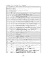
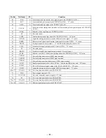
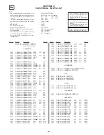
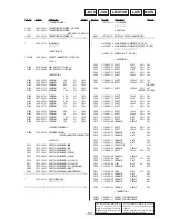
IC PIN FUNCTION DESCRIPTION
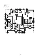
• MAINN BOARD IC501 CXP84340-075Q (SYSTEM CONTROLLER)
Pin No.
Pin Name
I/O
Function
1 to 5
A3 to A7
O
6
A12
O
7
A14
O
Address signal output to the static RAM (IC502)
8 to 11
A11 to A8
O
12
A13
O
13
WE
O
Data write enable signal output to the static RAM (IC502) “L” active
14
CE
O
Chip enable signal output to the static RAM (IC502) “H” active
15
KBCOUT
O
Serial data transfer clock signal output terminal Not used (open)
16
KBDOUT
O
Serial data output terminal Not used (open)
17
KBDIN
I
Serial data input terminal Not used (open)
18
FLDATA
O
Serial data output to the FL driver (IC701) and LED driver (IC702)
19
FLCLK
O
Serial data transfer clock signal output to the FL driver (IC701) and LED driver (IC702)
20
LEDLT
O
Serial data latch pulse output to the LED driver (IC702) “L” active
21
TBLL
O
Table motor drive signal (counterclockwise) output to the CXA1291P (IC503) “H” active
22
TBLR
O
Table motor drive signal (clockwise) output to the CXA1291P (IC503) “H” active
23
DRIN
O
Door motor drive signal (door close) output to the CXA1291P (IC503) “H” active
24
DROUT
O
Door motor drive signal (door open) output to the CXA1291P (IC503) “H” active
25
ADJ
I
Setting terminal for the test mode “L”: ADJ mode, Normally: fixed at “H”
26
LDIN
O
Loading motor drive signal (load-in direction) output to the CXA1291P (IC503) “H” active
27
LDOUT
O
Loading motor drive signal (load-out direction) output to the CXA1291P (IC503) “H” active
28
BUSOUT
O
Sircs remote control signal output for the S-LINK CONTROL A1 “H” active
29
SMUTE
O
Muting on/off control signal output terminal “H” active Not used (pull up)
30
RESET
I
System reset signal input from the reset signal generator (IC505) “L”: reset
For several hundreds msec. after the power supply rises, “L” is input, then it changes to “H”
31
EXTAL
I
Main system clock input terminal (10 MHz)
32
XTAL
O
Main system clock output terminal (10 MHz)
33
VSS
—
Ground terminal
34
TX
O
Sub system clock output terminal Not used (open)
35
TEX
I
Sub system clock input terminal Not used (fixed at “L”)
36
AVSS
—
Ground terminal (for A/D converter)
37
AVREF
I
Reference voltage (+5V) input terminal (for A/D converter)
38
D.SENS
I
Inputs the disc sensor (Q801) detection signal (A/D input)
39
DOORSW
I
Door open/close detect switch (S810) input (A/D input) “L”: open
40
CD1/2/3
I
COMMAND MODE switch (S901) input terminal (A/D input)
“L”: CD1, “H”: CD3 (CD2: center voltage input)
41
SW
I
Destination setting terminal (A/D input) Fixed at “L” in this set
42
KEY3
I
Key input terminal (A/D input)
p
,
P
,
·
, CLEAR, CHECK,
±
AMS,
≠
AMS, PUSH
ENTER keys input and rotary encoder jog dial pulse input (S611 to 617 and RE601)
43
KEY2
I
Key input terminal (A/D input)
§
OPEN/CLOSE, INPUT, MEMO SEARCH keys input and
rotary encoder jog dial pulse input (S621 to 623 and RE601)
44
KEY1
I
Key input terminal (A/D input)
I/
u
, TIME/TEXT, GROUP FILE, GROUP 8/7/6/5 keys input (S731 to 737)
45
KEY0
I
Key input terminal (A/D input)
REPEAT, PROGRAM, SHUFFLE, CONTINUE, GROUP 4/3/2/1 keys input (S721 to 728)
46
BUSIN
I
Sircs remote control signal input for the S-LINK CONTROL A1 “L” active
47
AMUTE
O
Muting on/off control signal output to the CXD2587Q (IC101) “H”: muting on


