background image

26

 GB

KLV-32/22T550A

4-153-893-

E1

(1)

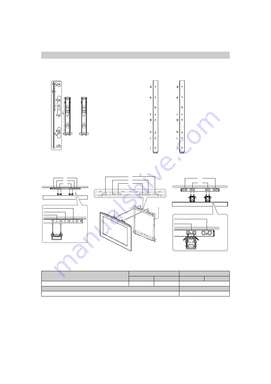
Screw and Hook locations diagram/table

Model Name

Screw location

Hook location

SU-WL500

SU-WL50B

SU-WL500

SU-WL50B

KLV-32T550A

e, g

e, h

c

SU-WL100

KLV-22T550A

b

b

*

a

*

b

a

*

c

b

*

a

*

c

b

c

b

a

a

c

a

b

c

c

b

a

Screw location

 - 

When installing the Mounting Hook on the TV.

SU-WL500:

Hook location

 - 

When installing the TV onto the Base Bracket.

SU-WL500:

Base Bracket

Hook

SU-WL50B:

SU-WL50B:

SU-WL100:

* Hook location “a” and “b” 

cannot be used for the 
models in the table below.

* Hook location “a” cannot be 

used for the models in the table 
below.

* Hook location “a” and “b” cannot be 

used for the models in the table below.

Summary of Contents for Bravia KLV-22T550A

Page 1: ... Sound Output 10 W 10 W 5 W 5 W Input Output jacks Antenna 75 ohm external terminal 1 Video input phono jack 1 Audio input phono jacks 500 mVrms Impedance 47 kilohms Supported formats 1080p 50 60 Hz 1080i 50 60 Hz 720p 50 60 Hz 576p 576i 480p 480i Y 1 Vp p 75 ohms 0 3V sync negative PB CB 0 7 Vp p 75 ohms PR CR 0 7 Vp p 75 ohms Audio input phono jacks 500 mVrms Impedance 47 kilohms Video output ph...

Page 2: ...oughly and retain it for future reference The illustrations used in this manual are of the KLV 32T550A unless otherwise stated HDMI the HDMI logo and High Definition Multimedia Interface are trademarks or registered trademarks of HDMI Licensing LLC BRAVIA and are trademarks of Sony Corporation Introduction Trademark information ...

Page 3: ...ptional Equipment Connecting optional equipment 12 Viewing pictures from the connected equipment 13 Viewing Twin Picture 14 Viewing PIP Picture in Picture 14 15 Using MENU Functions Navigating through menus 15 Listening to the FM Radio 15 Using the Favourite List 16 Settings adjustment 17 Picture menu 17 Sound menu 18 Screen menu 18 Set up menu 19 PC Settings menu 20 Channel Set up menu 21 Eco men...

Page 4: ... stand If using an electric screwdriver set the tightening torque at approximately 1 5N m 15kgf cm Ensure the AC power cord is away from screw holes during stand installation to avoid damage to the AC power cord 2 Connecting an antenna cable VCR Connecting an antenna cable Push and lift the cover to open 8 8 8 8 Connecting an antenna cable and VCR Antenna cable not supplied Antenna cable not suppl...

Page 5: ...te to turn on the TV When you turn on the TV for the first time the Language menu appears on the screen Follow the instructions on the screen 3 Press F f to select the language displayed on the menu screens then press 4 Press F f to select the country region then press 5 Press F f to select Home then press 6 Press G g to select OK then press The TV starts searching for all available channels If a ...

Page 6: ...ng 1 on the TV or is disconnected from the AC power outlet the initial set up procedure restarts the next time the TV is turned on Watching TV 1 Press 1 on the TV to turn on the TV 2 Press the number buttons or PROG to select a TV channel 3 Press 2 to adjust the volume Detaching the Table Top Stand from the TV Do not remove the Table Top Stand for any reason other than to wall mount the TV ...

Page 7: ...all the TV set as shown below AC power cord Handle the AC power cord and outlet as follows in order to avoid any risk of fire electrical shock or damage and or injuries Use only Sony supplied AC power cords not those of other brands Insert the plug fully into the AC power outlet Operate the TV set on a 110 240 V AC supply only When wiring cables be sure to unplug the AC power cord for your safety ...

Page 8: ...he picture or the picture may become dark This does not indicate a failure These phenomena disappear as the temperature rises Ghosting may occur when still pictures are displayed continuously It may disappear after a few moments The screen and cabinet get warm when this TV set is in use This is not a malfunction The LCD screen contains a small amount of liquid crystal Mercury is sometimes containe...

Page 9: ...elect OK Selects or adjusts items Confirms selected items 7 TOOLS page 10 8 MENU Displays or cancels the menu 9 Number buttons Selects channels For channel numbers 10 and above enter the next digit quickly page 21 In Text mode Enters the three digit page number to select the page q Favourite list Display the Favourite list that you have specified page 16 qa Previous channel Returns to the previous...

Page 10: ...etches the original picture to fill the screen vertically Full 2 Stretches the Full 1 picture horizontally to fill the 16 9 screen Using the Tools menu Options Description Picture Mode See page 17 Sound Mode See page 18 Intelligent Picture See page 21 MPEG Noise Reduction See page 17 Speaker See page 19 Add to Favourites You can add the current channel to the favourite list Sleep Timer See page 19...

Page 11: ... menu Selects the menu or option and confirms the setting 4 2 Increases or decreases the volume In TV menu Moves through the options right or left 5 PROG Selects the next or previous channel In TV menu Moves through the options up or down 6 Remote sensor Receives IR signals from the remote 7 Timer indicator Lights up in amber when the timer is set page 19 8 1 Power indicator Standby indicator Ligh...

Page 12: ...ing optional equipment You can connect a wide range of optional equipment to your TV S VHS Hi8 DVC camcorder Digital video camcorder DVD player with HDMI output Home theatre system Blu ray disc player Video game equipment DVD player without component video output VCR DVD player with component video output DVD recorder PC VCR For service use only ...

Page 13: ... jack to record the image from the TV Connect to the audio output jacks to record the sound from the TV on DVD recorder or VCR To turn off the sound of the TV speakers set Speaker to Audio System page 19 If you connect mono equipment connect to the L jack The monitor output jacks cannot support Component HDMI and PC signals source pictures also digital audio signal for sound C Component Connect to...

Page 14: ...n Picture from the Tools menu page 10 Viewing PIP Picture in Picture You can view two pictures PC input and TV programme on the screen simultaneously Connect a PC page 12 and make sure that images from a PC appear on the screen page 13 1 Press Two pictures are displayed simultaneously 2 Press number buttons or PROG to select the TV channel To return to single picture mode Press or RETURN You canno...

Page 15: ...select Edit Programme Labels then see page 21 3 External Inputs Selects equipment connected to your TV To watch the desired external input select the input source then press To assign a label to an external input select Edit Video Labels then see page 19 4 FM Radio Listens to the FM Radio page 15 5 Settings Displays the Settings menu where most of the advanced settings and adjustments are performe...

Page 16: ...ppears display the Channel Set up menu and select FM Radio Set up to preset the desired FM radio stations page 22 To Do this The Favourite feature lets you select programmes from a list of up to 16 favourite channels that you specify 1 Press MENU 2 Press F f to select Favourites then press 3 Perform the desired operation as shown in the following table or displayed on the screen Favourite List To ...

Page 17: ... Hue can only be adjusted for an NTSC colour system e g U S A video tapes Colour Temperature Adjusts the whiteness of the picture Cool Gives the white colours a blue tint Neutral Gives the white colours a neutral tint Warm 1 Warm 2 Gives the white colours a red tint Warm 2 gives a redder tint than Warm 1 Warm 1 and Warm 2 are not available when Picture Mode is set to Vivid Sharpness Sharpens or so...

Page 18: ... select Mono The sound becomes monaural but the noise is reduced The Dual Sound setting is memorised for each programme position You cannot receive a stereo broadcast signal when Mono is selected for the programme position z If you select other equipment connected to the TV set Dual Sound to Stereo Main or Sub However when the external equipment connected to the HDMI jack is selected this is fixed...

Page 19: ...ssign a name to connected equipment Edit Creates your own label Follow steps 2 to 4 of Programme Labels page 21 Skip Skips an unnecessary input source Speaker Turns on off the TV s internal speakers TV Speaker The TV speakers are turned on in order to listen to the TV s sound through the TV speakers Audio System The TV speakers are turned off in order to listen to the TV s sound only through your ...

Page 20: ... the TV off during this period it takes about 30 seconds or press any buttons PC Settings menu Wide Mode Selects a screen mode for displaying input from your PC see page 10 Normal Displays the picture in its original size Full 1 Enlarges the picture to fill the display area keeping its original horizontal to vertical aspect ratio Full 2 Enlarges the picture to fill the display area Reset Resets al...

Page 21: ...elect the new position for your channel then press Programme Labels Assigns a channel name of your choice up to five letters or numbers The name will be displayed briefly on the screen when the channel is selected 1 Press F f to select the channel you want to name then press 2 Press F f to select the desired letter or number _ for a blank space then press g If you input a wrong character Press G g...

Page 22: ...selected the fine tuning is performed automatically Skip Skips unused channels when you press PROG to select channels You can still select a skipped channel using the number buttons Colour System Selects the colour system Auto PAL SECAM NTSC3 58 NTSC4 43 or PAL60 according to the channel Signal Booster Intelligent Signal Booster Improves the picture quality if the TV signal is too strong or weak P...

Page 23: ...ving Selects the power saving mode to reduce the power consumption of the TV Choose either Standard Power or Reduced Power Idle TV Standby Selects the time 1h 2h or 3h to set the TV into standby mode automatically if you do not operate the TV for the specified period of time ...

Page 24: ... with the Wall Mount Bracket to properly carry out the installation Refer to Detaching the Table Top Stand from the TV page 6 Refer to TV installation dimensions table page 25 Refer to Screw and Hook locations diagram table page 26 Place the TV on the Table Top Stand when securing the Mounting Hook 2 0 1 5 1 0 5 0 2 0 1 5 1 0 5 0 Square hole SU WL500 Mounting Hook Screw PSW 6 16 Mounting Hook Scre...

Page 25: ...n dimensions table b b a c a c Screen centre point SU WL500 SU WL50B Screen centre point Model Name Display dimensions Screen centre dimension Length for each mounting angle Angle 0 Angle 20 A B C D E F G H SU WL500 SU WL50B SU WL500 SU WL50B SU WL500 SU WL50B SU WL500 only KLV 32T550A 920 527 172 200 442 470 157 157 480 499 307 125 SU WL100 Screen centre point Model Name Display dimensions Screen...

Page 26: ... b c b a a c a b c c b a Screw location When installing the Mounting Hook on the TV SU WL500 Hook location When installing the TV onto the Base Bracket SU WL500 Base Bracket Hook SU WL50B SU WL50B SU WL100 Hook location a and b cannot be used for the models in the table below Hook location a cannot be used for the models in the table below Hook location a and b cannot be used for the models in the...

Page 27: ...of its serviceable life three to five years in normal use one to two years at the seaside Distorted picture dotted lines or stripes Keep the TV away from electrical noise sources such as cars motorcycles hair dryers or optional equipment When installing optional equipment leave some space between the optional equipment and the TV Check the antenna cable connection Keep the antenna cable away from ...

Reviews: