background image

 131 

KDF-46E2000/46E2010/50E2000/50E2010/55E2000/55E2010

KDF-46E2000/46E2010/50E2000/50E2010/55E2000/55E2010


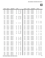
REF. NO.  

PART NO. 

DESCRIPTION 

 VALUES   


REF. NO.  

PART NO. 

DESCRIPTION 

 VALUES   

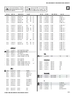
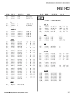
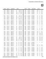
 D8424  8-719-977-28  DIODE 

DTZ10B

 D8425  8-719-069-55  DIODE 

UDZSTE-175.6B

 D8426  8-719-977-28  DIODE 

DTZ10B

 D8427  8-719-977-28  DIODE 

DTZ10B

 D8428  8-719-083-57  DIODE 

UDZSTE-173.6B

 D8429  8-719-083-57  DIODE 

UDZSTE-173.6B

IC

 IC8402 8-753-232-63  IC 

CXA2229Q-T6

 IC8403 8-752-107-98  IC 

CXA2188Q-T4

 IC8404 8-759-278-58  IC 

NJM4558V-TE2

JACK


J8400 

1-780-271-11 

S CONNECTOR BLOCK

 J8401  1-819-357-11  PHONO 

JACK 

10P

* J8402  1-819-358-11  PHONO 

JACK

* J8403  1-819-358-11  PHONO 

JACK

COIL

 L8401  1-469-555-21  INDUCTOR 

10µH

 L8402  1-469-555-21  INDUCTOR 

10µH

 L8403  1-469-555-21  INDUCTOR 

10µH

 L8404  1-469-555-21  INDUCTOR 

10µH

 L8405  1-469-555-21  INDUCTOR 

10µH

 L8406  1-469-555-21  INDUCTOR 

10µH

TRANSISTOR

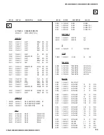
 Q8400  8-729-120-28  TRANSISTOR 

2SC1623-L5L6

 Q8401  8-729-120-28  TRANSISTOR 

2SC1623-L5L6

 Q8402  8-729-120-28  TRANSISTOR 

2SC1623-L5L6

 Q8403  8-729-120-28  TRANSISTOR 

2SC1623-L5L6

 Q8405  6-551-390-01  TRANSISTOR 

RT1A3906-T122-1

 Q8406  6-551-390-01  TRANSISTOR 

RT1A3906-T122-1

 Q8407  6-551-390-01  TRANSISTOR 

RT1A3906-T122-1

 Q8408  8-729-600-22  TRANSISTOR 

2SA1235-F

 Q8409  8-729-600-22  TRANSISTOR 

2SA1235-F

 Q8410  8-729-120-28  TRANSISTOR 

2SC1623-L5L6

 Q8411  8-729-120-28  TRANSISTOR 

2SC1623-L5L6

 Q8412  8-729-120-28  TRANSISTOR 

2SC1623-L5L6

 Q8413  8-729-600-22  TRANSISTOR 

2SA1235-F

 Q8414  8-729-600-22  TRANSISTOR 

2SA1235-F

 Q8607  8-729-600-22  TRANSISTOR 

2SA1235-F

RESISTOR

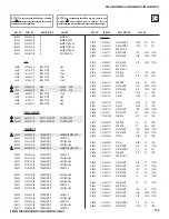
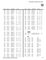
 R8401  1-218-871-11  METAL 

CHIP 

10K  0.50% 

1/10W

 R8402  1-218-831-11  METAL 

CHIP 

220  0.50% 

1/10W

 R8404  1-218-831-11  METAL 

CHIP 

220  0.50% 

1/10W

 R8405  1-216-809-11  METAL 

CHIP 

100  5% 1/10W

 R8406  1-218-871-11  METAL 

CHIP 

10K  0.50% 

1/10W

 R8407  1-216-821-11  METAL 

CHIP 

1K  5% 1/10W

 R8409  1-218-871-11  METAL 

CHIP 

10K  0.50% 

1/10W

 R8410  1-218-831-11  METAL 

CHIP 

220  0.50% 

1/10W

 R8411  1-218-831-11  METAL 

CHIP 

220  0.50% 

1/10W

 R8412  1-218-831-11  METAL 

CHIP 

220  0.50% 

1/10W

 R8413  1-216-853-11  METAL 

CHIP 

470K  5% 1/10W

 R8414  1-216-809-11  METAL 

CHIP 

100  5% 1/10W

 R8415  1-218-871-11  METAL 

CHIP 

10K  0.50% 

1/10W

 R8416  1-216-821-11  METAL 

CHIP 

1K  5% 1/10W

 R8417  1-216-809-11  METAL 

CHIP 

100  5% 1/10W

 R8420  1-216-809-11  METAL 

CHIP 

100  5% 1/10W

 R8422  1-218-831-11  METAL 

CHIP 

220  0.50% 

1/10W

 R8424  1-216-809-11  METAL 

CHIP 

100  5% 1/10W

 R8425  1-216-809-11  METAL 

CHIP 

100  5% 1/10W

 R8427  1-216-829-11  METAL 

CHIP 

4.7K  5% 1/10W

 R8428  1-216-815-11  METAL 

CHIP 

330  5% 1/10W

 R8429  1-216-809-11  METAL 

CHIP 

100  5% 1/10W

 R8430  1-218-871-11  METAL 

CHIP 

10K  0.50% 

1/10W

 R8431  1-216-815-11  METAL 

CHIP 

330  5% 1/10W

 R8432  1-216-807-11  METAL 

CHIP 

68 

5% 1/10W

 R8433  1-216-807-11  METAL 

CHIP 

68 

5% 1/10W

 R8434  1-216-809-11  METAL 

CHIP 

100  5% 1/10W

 R8435  1-216-809-11  METAL 

CHIP 

100  5% 1/10W

 R8436  1-216-864-11  SHORT 

CHIP

 R8437  1-216-864-11  SHORT 

CHIP

 R8442  1-216-864-11  SHORT 

CHIP

 R8443  1-216-864-11  SHORT 

CHIP

 R8456  1-216-864-11  SHORT 

CHIP

 R8457  1-216-864-11  SHORT 

CHIP

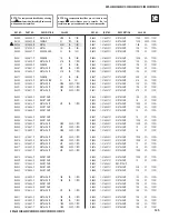
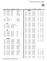
 R8464  1-216-829-11  METAL 

CHIP 

4.7K  5% 1/10W

 R8465  1-216-829-11  METAL 

CHIP 

4.7K  5% 1/10W

 R8466  1-216-829-11  METAL 

CHIP 

4.7K  5% 1/10W

 R8467  1-216-829-11  METAL 

CHIP 

4.7K  5% 1/10W

 R8468  1-216-829-11  METAL 

CHIP 

4.7K  5% 1/10W

 R8469  1-216-829-11  METAL 

CHIP 

4.7K  5% 1/10W

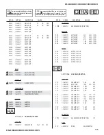
 R8470  1-216-853-11  METAL 

CHIP 

470K  5% 1/10W

 R8471  1-216-853-11  METAL 

CHIP 

470K  5% 1/10W

U

Summary of Contents for Bravia KDF-50E2010

Page 1: ...10 MEXICO KDF 50E2000 RM YD010 US CND KDF 50E2010 RM YD010 MEXICO KDF 55E2000 RM YD010 US CND KDF 55E2010 RM YD010 MEXICO HISTORY INFORMATION FOR THE FOLLOWING MANUAL ORIGINAL MANUAL ISSUE DATE 5 2006 UPDATED ITEM REVISION DATE SUBJECT 5 2006 No revisions or updates are applicable at this time 6 2006 Replaced Pages 70 72 73 to include Power supply note ...

Page 2: ...ME REMOTE COMMANDER DESTINATION 9 883 709 02 KDF 46E2000 RM YD010 US CND KDF 46E2010 RM YD010 MEXICO KDF 50E2000 RM YD010 US CND KDF 50E2010 RM YD010 MEXICO KDF 55E2000 RM YD010 US CND KDF 55E2010 RM YD010 MEXICO SelfDiagnosis Supported model KDF 50E2010 RM YD010 ...

Page 3: ... Changes 51 2 6 Resetting Wega User Menu to Factory Defaults 51 2 7 H V Center Confirmation and Adjustments 52 2 8 IRIS Adjustments 52 SECTION 3 DIAGRAMS 53 3 1 Circuit Boards Location 53 3 2 Printed Wiring Boards and Schematic Diagrams Information 53 3 3 Signal Flow Block Diagram 55 3 4 Schematics and Supporting Information 56 A Board Schematic Diagram 56 B Board Schematic Diagram 1 of 11 58 B Boa...

Page 4: ...mm 1184 x 827 x 408 mm 1301 x 907 x 442 mm in 43 1 4 x 30 1 4 x 15 1 8 in 46 5 8 x 32 5 8 x 16 1 8 in 51 1 4 x 35 3 4 x 17 1 2 in Mass kg 27 kg 29 3 kg 34 kg lbs 59 lbs 5 oz 64 lbs 7 oz 75 lbs 12W L 12W R Trademark Information As an ENERGY STAR Partner Sony Corporation has determined that this product meets the ENERGY STAR guidelines for energy efficiency ENERGY STAR is a U S registered mark TruSu...

Page 5: ...000 55E2010 Only Antenna 75 ohm external antenna terminal for VHF UHF Projection System 3 LCD Panels 1 lens projection system LCD Panel 0 73 inch TFT LCD panel 1 280 x 720 pixels Projection Lens High Performance large diameter hybrid lens F2 4 Lamp 100W XL 2400 Ultra High Pressure Lamp Supplied Accessories Remote Commander RM YD010 Two Size AA R6 Batteries Operating Instructions Quick Setup Guide ...

Page 6: ...itical components are replaced or improper operation is suspected ATTENTION Ces instructions de service sont à l usage du personnel de service qualifié seulement Pour prévenir le risque de choc électrique ne pas faire l entretien autre que celui contenu dans le Mode d emploi à moins que vous soyez qualifié faire ainsi Afin d eviter tout risque d electrocution provenant d un chássis sous tension un tr...

Page 7: ...om all exposed metal parts to any exposed metal part having a return to chassis must not exceed 0 5 mA 500 microamperes Leakage current can be measured by any one of three methods 1 A commercial leakage tester such as the Simpson 229 or RCA WT 540A Follow the manufacturers instructions to use these instructions 2 A battery operated AC milliampmeter The Data Precision 245 digital multimeter is suit...

Page 8: ... the first of the problem areas If the errors occur simultaneously the one that corresponds to the fewest flashes is identified first Results for all of the following diagnostic items are displayed on screen No error has occurred if the screen displays a 0 Detected symptoms Lamp cover Lamp position error Temp error 3 times 2 times 4 times 5 times 6 times 8 times Lamp cover is not securely attached T1 ...

Page 9: ...ional power off and or picture mute the Self Diagnostic screen display is useful to specify the cause VIEWING THE SELF DIAGNOSTIC SCREEN 1 TV must be in standby mode Power off 2 Press the following buttons on the Remote Commander within a second of each other DISPLAY Channel 5 Volume POWER NOTE This differs from the method of accessing service mode which is Volume Sample Self Diagnostic Screen Dis...

Page 10: ...S Category is not displayed press 2 or 5 on the Remote Comman until the STATUS Category is displayed 5 The SHUTDOWN_LOG1 Adjustment Item is the first item of the STATUS Category and contains the first error the set detected 6 To view additional errors press 1 until the SHUTDOWN_LOG2 Adjustment Item is displayed 7 After repairing the errors proceed to Clearling the Self Diagnostic Screen CLEARING THE...

Page 11: ...KDF 46E2000 46E2010 50E2000 50E2010 55E2000 55E2010 KDF 46E2000 46E2010 50E2000 50E2010 55E2000 55E2010 11 SELF DIAGNOSTIC FUNCTION OPERATION Z Z Z Z Z Z Z Z Z Z Z ...

Page 12: ...S2 BOARD IC160 TEMP SENSOR IC110 TEMP HB BOARD SENSOR G BOARD B BOARD 137 I_FAN_PROT 129 126 LB ERROR D_OVP 10 5V I2C I2C I2C I2C T1 BOARD T2 BOARD 3 1 SW 3 SW 1 HV DET LAMP DRIVER 150 I_LAMP_COVER I_LAMP_PROT 151 I_HV_DET 152 IC3002 TV Micro computer 3 3 2 2 CN6800 CN6805 CN6801 CN6802 9 8 10 11 7 1 CN6804 CN6803 10 6 12 CN6904 2 CN6904 CN3002 2 CN3002 12 6 10 ...

Page 13: ...al hours 256 Total hours 160 5 Do one of the following a If you have replaced the lamp proceed to step 4 of Resetting the Lamp Time b If you have not replaced the lamp turn off the set by pressing POWER RESETTING THE LAMP TIME When replacing the lamp use the following to reset the lamp time 1 If the Self Diagnostic screen is already displayed proceed to step 4 If not Power off Set to Standby mode ...

Page 14: ...Screwdriver Needle Nose Pliers Small Flathead Screwdriver or Jewelers Screwdriver LIFT ONE SIDE AT A TIME BY PUSHING TAB IN WITH SMALL SCREWDRIVER TYPE 1 TYPE 2 SQUEEZE DOWN ON TAB TO RELEASE SQUEEZE LOCKING TAB TOWARDS CONNECTOR BEFORE PULLING FREE TYPE 3 CAUTION IF THE TYPE 2 FEMALE CONNECTOR HAS A SLOT AS SHOWN MAKE SURE THE LOCK TAB SEATS INSIDE THIS SLOT Use caution not to rock the Type 2 or ...

Page 15: ... 2 REAR COVER REMOVAL Lamp door Turn the handle until it is in the CLOSE position Lamp door When reassembling the rear cover be sure to securely lock the lamp door to avoid a lamp cover failure warning 1 Pull down the claw to release the Lamp Door 2 Remove the Lamp Door 3 Remove 13 screws BVTP2 4X16 to remove the Rear Cover ...

Page 16: ...ard 4 Release wires from purse locks 5 Gently pull chassis out towards the right of the TV to access connectors on B Block Assembly 6 Disconnect CN308 and CN3750 on B Block Assembly 7 Release connectors from Wire Holders 8 Remove 4 screws to release the G Board 9 Remove 6 screws to detach Metal Shield from G Board Using the picture above as a reference disconnect CN6018 CN6801 CN6804 CN6803 CN6800...

Page 17: ...t the coaxial cable to release the antenna switch Remove 3 screws then gently lift the A Block Assembly up to disconnect CN1002 from the B Block Assembly 3 Using caution remove the LVDS cable from the B Board then remove 1 screw connecting the B Block Assy K Board to the Main Bracket and lift up on the tab of the Main Bracket to release the B Block Assembly 4 Using tweezers gently pinch the fan da...

Page 18: ...Right Stay 2 Disconnect CN150 T1 Board 3 Disconnect CN155 T2 Board 4 Disconnect the Termal Fuse connector 5 Disconnect CN160 S2 Board 6 Remove 2 screws then pull out the fan cover 7 Turn the fan cover over to remove the T1 Board and S2 Board 8 Using caution remove the LVDS cable and 2 screws 9 Remove 2 screws to release the Lamp Block Assembly and the Optical Block assembly from the cabinet 0 Gent...

Page 19: ...010 50E2000 50E2010 55E2000 55E2010 19 2 3 1 6 1 LAMP CONNECTOR AND T2 BOARD REMOVAL 1 Pull retaining clip outward to release and drop the high voltage connector and the T2 Bracket 2 Separate the HV Connector from the bracket 3 Remove 1 screw to release the T2 Board 1 1 ...

Page 20: ...atch for fan grommets NOTE Reinsert the fan grommets when replacing the fan 2 3 4 5 6 1 1 From the inside of the assembly release the 3 claws securing the fan duct then remove the fan duct by grasping as shown 2 Remove 1 screw 3 Release 3 clips to detach cover 4 Remove Fan 5 Release wire from wire holders 6 Remove 2 screws 1 6 2 LAMP DRIVER FAN REMOVAL ...

Page 21: ...4 Lift out to remove HC Board 1 4 3 1 8 HA BOARD AND HB BOARD REMOVAL 4 3 5 2 HA Board HB Board 1 1 Remove 2 screws from inside the front panel 2 Using a screwdriver gently push through the hole to release the speaker grill 3 Firmly pull on the speaker grill to detach from the cabinet 4 Disconnect CN7000 and remove 2 screws to release the HA Board 5 Disconnect CN7020 and remove 2 screws to release...

Page 22: ...4 1 Release the wire harness from the purse locks 2 Disconnect the CN2500 from the K Board 3 Remove 15 screws to detach the Mirror Cover Assembly from the Screen Frame Assembly 4 Remove 4 screws to detach the Screen Frame Assembly from the front bezel 5 Gently pull the Screen Frame Assembly forward 6 Remove 20 screws from the screen frame to release the disfussion plates Be sure to keep the retain...

Page 23: ...dels only 3 Using caution gently lift the mirror up and out of the mirror cover Slide the mirror up and to one side on the 55 model to release it from the mirror holders 4 Remove 4 screws to detach the front of the Mirror Cover Assembly from the cabinet 5 Remove 2 screws from back of the cover and then lift the Mirror Cover Assembly off of the cabinet 5 CAUTION When removing the Mirror Cover Assem...

Page 24: ...s Lamp Driver Leads as shown below to wire holders After Installing Duct Block assy to Optical Block Dress TOP Lamp Lead to Purse Lock on C Shield 1 910 024 31 Connector Assy should be dressed around Heat Sink and around Duct Block Cover as shown above Dress Bottom Lamp Driver Lead as shown to wire holder on Duct Block Assy BALLAST WIRE DRESSING ...

Page 25: ...0E2000 50E2010 55E2000 55E2010 KDF 46E2000 46E2010 50E2000 50E2010 55E2000 55E2010 25 1 910 024 31 Connector Assy should be dressed around Heat Sink and around Duct Block Cover as shown above BALLAST WIRE DRESSING CONTINUED ...

Page 26: ...8400 U and CN3008 B to purse lock on bottom block as shown Loop Video 2 Connector before installing into Purse Lock as shown to avoid Connector assy from Touching K Board Heat Sink ONLY FOR 46 and 50 models Install Ferrite Clamp 154383011 to the following Connector Assys 1 Speaker Conn Assy 2 HA HB Conn Assy 3 HC Conn Assy BOTTOM BLOCK WIRE DRESSING ...

Page 27: ...2000 50E2010 55E2000 55E2010 27 Install Conn Assy 1 910 024 21 to FAN1 Optical Block Fan Dress 15P CN9000 C LVDS Connector and Fan Connector to Purse Lock on C Shield Route Optical Block Fan to Wire Holder to avoid being Pinched when G Shield is installed C BLOCK WIRE DRESSING ...

Page 28: ...NG Dress the following Connector Assys to Purse Lock on Duct Block Assy 1 CN150 T1 2 X1 Ballast 3 X2 Ballast Note Duct Block Fan is not installed to Purse Lock Dress the following Connector Assys to Wire Holder on Bottom Block 1 1 910 024 29 2 X1 Ballast 3 X2 Ballast 4 Duct Block Assy Fan 5 Optical Block Fan Route Lamp Fan inside of 1 910 024 29 and Inside of X2 Ballast Power DUCT BLOCK ASSEMBLY W...

Page 29: ...e pin holder 1 LVDS and 8P CN6009 G 2 LVDS 8P CN6009 and 7P CN3004 B 3 LVDS and 7P CN3004 B Ensure wires are dressed to the side of the G Board as shown 3 1 2 G BOARD WIRE DRESSING Install Purse Lock 404928101 PURSE LOCK DIA 11 Purse lock should hold the following 32P Conn Assy G to B 3P Conn Assy G to K 3P Conn Assy G to ANT SWT 3P Conn Assy G to B Blk FAN After installing Purse Lock ensure open ...

Page 30: ...APPLY HIMELONE TAPE AS SHOWN ABOVE AND DRESS IRIS CONNECTOR ASSY TO WIRE HOLDER AS SHOWN BELOW APPLY HIMELONE TAPE TO SECURE IRIS CON NECTOR AS SHOWN ABOVE APPLY TAPE SO THAT THE CONNECTOR ASSEM BLY WILL NOT BE IN SHADED AREA ABOVE IF CONNECTOR ASSEMBLY IS IN THE SHADED ARER IT WILL GET PINCHED BETWEEN THE OPTICAL BLOCK ASSEMBLY AND THE BOTTOM BLOCK ASSEMBLY WHEN INSTALLED ...

Page 31: ...0E2000 50E2010 55E2000 55E2010 31 x Secure Ring Terminal of 1 910 016 90 to G Block as shown above x Install Faston Terminal to Antenna Switch Note Orientation of ring terminal should be towards the top of the set 1 910 016 90 OPTICAL BLOCK ASSEMBLY LIGHTNING GROUND POSITION ...

Page 32: ...00 55E2010 KDF 46E2000 46E2010 50E2000 50E2010 55E2000 55E2010 32 For 55 MUST use 2 screws on each side total 4 screws to secure Speaker Grill to Screen Frame For 50 and 46 use only 1 screws each side total 2 screws SPEAKER GRILL WIRE DRESSING ...

Page 33: ...50E2000 50E2010 55E2000 55E2010 KDF 46E2000 46E2010 50E2000 50E2010 55E2000 55E2010 33 See above for Connector Assy Routing of CN110 HB See above for Connector Assy Routing of CN100 HA SPEAKER GRILL WIRE DRESSING CONTINUED ...

Page 34: ...6E2000 46E2010 50E2000 50E2010 55E2000 55E2010 34 SPEAKER GRILL WIRE DRESSING CONTINUED Dress HA HB Connector Assy to Wire holder as shown above When routing HA HB Connector Assy through Wire Holder RED tape should be approximately in the position shown above ...

Page 35: ...NG CONTINUED 1 Use Holder M3 Wire 2 screw to wire dress as sh 2 Wire must enter from the Holder 2 599 956 01 as s 3 Must pull wire to the right from wire assy around C and Cable Holder area 1 2 3 NO Sound Cushion on 55 and 46 Speaker Grill 594 860 01 and 3x12 hown e bottom of Cable shown t to minimize sound vib Control Tray Bracket ...

Page 36: ...2000 50E2010 55E2000 55E2010 KDF 46E2000 46E2010 50E2000 50E2010 55E2000 55E2010 36 SPEAKER GRILL ASSEMBLY CUSHIONS Add 2 638 237 02 Cushion Sound SF to 55 Speaker Grill 2 671 852 Align Sound SF Cushion to the lines as shown ...

Page 37: ...er bracket and then Himelon Tape should be installed to secure the wire as shown Wire Should be pulled so that there is no excess wire THIS IS VERY IMPORTANT TO AVOID NOISE DUE TO SPEAKER VIBRATION Tape should wrap around bracket as shown to the right and securely hold the speaker wire so that it does not move once the tape is applied SPEAKER WIRE DRESSING ...

Page 38: ...0 55E2010 38 1 2 3 4 Speaker Bracket must be secured following the above Screw Order On Left Speaker Secure Speaker wire as shown below using 265206401 TAPE HIMELON 20X40 Note PCN MB607734 Shows different Tape position please disregard that location and use above SPEAKER WIRE DRESSING CONTINUED ...

Page 39: ...KDF 46E2000 46E2010 50E2000 50E2010 55E2000 55E2010 KDF 46E2000 46E2010 50E2000 50E2010 55E2000 55E2010 39 RIGHT SPEAKER WIRE DRESSING ...

Page 40: ...KDF 46E2000 46E2010 50E2000 50E2010 55E2000 55E2010 KDF 46E2000 46E2010 50E2000 50E2010 55E2000 55E2010 40 LEFT SPEAKER WIRE DRESSING ...

Page 41: ... 50E2000 50E2010 55E2000 55E2010 KDF 46E2000 46E2010 50E2000 50E2010 55E2000 55E2010 41 All these applies for 55 46 For 50 this starts from MP set 1 no need to re work PP and PVT sets LEFT SPEAKER WIRE DRESSING CONTINUED ...

Page 42: ...ng pinched when Chassis is installed into Bottom Block Himelon Tape should secure the 2 connectors coming from the Ballast the Fan connector assy and 3P Connector Assy from T1 ONLY FOR 50 MODELS Himelon Tape should secure Duct Block Assy fan Connector as shown Connector Assy should be pulled tight against fan Duct in order to avoid vibration of wire against bracket BOTTOM BLOCK ASSEMBLY HIMELON TA...

Page 43: ... and dress to Purse Lock Loop Video 2 Connector before installing into Purse Locak as shown to avoid Connector assy from Touching K Board Heat Sink ONLY FOR 46 and 50 models Ensure no excess wire is hanging loose in this area THIS IS VERY IMPORTANT TO AVOID NOISE DUE TO SPEAKER VIBRATION Before installing chassis Dress CN3004 B CN8400 U and CN3008 B to purse lock on bottom block as shown BOTTOM BL...

Page 44: ...s 15P connector Assy LVDS Connector Assy and Optical Block Fan Connector Assy to Purse Lock as shown 435591211 PURSE LOCK DIA 11 265206401 TAPE HIMELON 20X40 Apply Himelon to K Board Power Connector Assy and tape to B Shield as shown Tape must be placed in this position to avoid connector from being pinched by U bracket when installed CHASSIS WIRE DRESSING CAUTION POINTS ...

Page 45: ...0 55E2010 KDF 46E2000 46E2010 50E2000 50E2010 55E2000 55E2010 45 When Pulling the damper through the fan be careful not to use excessive force which may break the damper in this area 269304701 GASKET 5 X 10 X 30 DAMPER AND GASKET CAUTION POINTS ...

Page 46: ...CN6009 G 2 LVDS 8P CN6009 and 7P CN3004 B 3 LVDS and 7P CN3004 B 1 2 3 When Dressing 1 910 024 29 and Duct Block Fan to wire Holder ensure the wires are not positioned above capacitors on G This is to avoid the connector wires from touching the rear cover Install Purse Lock 404928101 PURSE LOCK DIA 11 Purselock should hold the following 32P Conn Assy G to B 3P Conn Assy G to K 3P Conn Assy G to AN...

Page 47: ...nd then Himelon Tape should be installed to secure the wire as shown Wire Should be pulled so that there is no excess wire THIS IS VERY IMPORTANT TO AVOID NOISE DUE TO SPEAKER VIBRATION Tape should wrap around bracket as shown to the right and securely hold the speaker wire so that it does not move once the tape is applied RIGHT SPEAKER WIRE DRESSING CAUTION POINTS ...

Page 48: ...efore applying tape ensure as much slack is taken out of the wire by pulling it towards the negative terminal Wire Holder is installed on speaker bracket as shown Remove as much slack out of wire before dressing it to the wire holder ONLY FOR 50 MODELS Pull wire in direction of arrow to take out slack 265206401 TAPE HIMELON 20X40 After dressing to wire holder dress wire through speaker bracket as ...

Page 49: ...S L O O T TV VIDEO DVR VCR SAT CABLE FUNCTION TV BD DVD POWER TV POWER JUMP ANT FREEZE SOUND PICTURE WIDE VISUAL SEARCH PAUSE PLAY STOP REC REC PAUSE REC STOP TOP MENU MENU F1 F2 G D I U E DI P S Y A L REPLAY ADVANCE NEXT PREV TV CH VOL MENU MUTING BD DVD MODE SLEEP SURROUND Displays Service Menus DISPLAY VOLUME POWER JUMP RM YD010 The first service menu TV displays SECTION 2 CIRCUIT ADJUSTMENTS 2 ...

Page 50: ...change the Adjustment Item press 1 or 4 on the Remote Commander 4 To change the Data Value press 3 or 6 on the Remote Commander Note To go back to the last saved Data Value press 0 then ENT on the Remote Commander to read the memory 5 To save the changes press MUTING then ENT to write into memory 6 To exit service mode turn the power off by pressing POWER Wait 2 minutes before restarting the set t...

Page 51: ...RIFYING SERVICE DATA CHANGES 1 After completing all adjustments turn the set off with the Remote Commander and WAIT for the fans to turn off before proceeding to the next step Note It may take up to two minutes for the fans to stop Caution To avoid over heating the lamp do not unplug the set until the fans have stopped 2 After the fans have stopped unplug the set from the AC outlet then plug the s...

Page 52: ... item f Press 3 to increase the data value or 6 to decrease the data value g To save the changes press MUTING then ENT to write into memory h To exit service mode turn the power off by pressing POWER Wait 2 minutes before restarting the set to allow the fans to completely shut down or the Service Menu will appear on the screen K DHPS 22 for H center DVPS 23 for V center DVPS DHPS 2 8 IRIS ADJUSTME...

Page 53: ... noted Readings are taken with a color bar signal input Readings are taken with a 10MΩ digital multimeter Voltages are DC with respect to ground unless otherwise noted Voltage variations may be noted due to normal production tolerances All voltages are in V S Measurement impossibility B line B line Actual measured value may be different signal path RF Circled numbers are waveform references The co...

Page 54: ...1 wa B1 E1 C2 B2 C1 E2 G S S D G D B1 E1 C2 B2 C1 E2 B1 E2 C2 C1 B2 E2 B1 C1 C2 E1 B2 C2 B1 C1 E2 E1 B2 C2 B1 C1 E2 B2 E1 C2 Ver 1 5 Transistor FET Transistor Transistor Transistor Transistor Transistor Transistor Transistor Transistor Transistor Discrete semiconductot Chip semiconductors that are not actually used are included Diode Diode Diode Diode Diode Diode Diode Diode Diode Diode Source Sou...

Page 55: ...4Mb DCP CXD9690 LVDS Tx R LCD A7001 PAWN CXD9809 G LCD A7001 B LCD A7001 NVM 256k NVM 32k C EDID 2k EDID 2k Audio ADC Audio OUT Linear AMP TA8258 NVM 128k A Audio DAC G CXA1875 I2S Graphics LPF SM5302 TMP75 FAN TMP75 LAMP S2 HB LVDS Rx APL IRIS 656 8bit sync YPbPr RGB Audio SW CD4052 FAN S VIDEO1 VIDEO3 COMP1 COMP3 AUDIO4 For DVI VIDEO2 COMP2 K HC DeMUX FLIPFLOP MUX 24bit RGB 13bit HDMI2 HDMI1 Dig...

Page 56: ... C1029 1608 50V 1000p B C1030 0uH FB1005 0uH FB1006 1 10W RN CP 5 100 R1032 2SC3052EF T1 LEF Q1001 1 10W RN CP 5 15k R1033 2012 10V 2 2 B C1032 1608 50V 1000p B C1035 1 10W RN CP 5 10k R1034 1608 16V 0 1 B C1024 1 10W RN CP 5 100 R1038 CHIP 0 R1039 2SA1235TP 1EF Q1002 2SC3052EF T1 LEF Q1003 2SC3052EF T1 LEF Q1004 1608 1 10W RN CP 5 R1040 100 1 10W RN CP 5 100 R1041 1 10W RN CP 5 1k R1042 1 10W RN ...

Page 57: ...007 R1011 R1010 R1014 C1025 FB1000 C1002 L1000 R1008 R1012 22 21 2 1 CN1002 1 869 670 11 172753811 C1026 C1027 C1028 C1001 R1005 C1047 R1006 C1000 C1042 C1043 L1009 R1004 C1029 C1030 L1007 C1041 C1044 R1009 R1013 R1003 C1032 C1033 C1045 C1048 Q1001 R1033 R1047 C1037 C1038 C1040 C1039 FB1008 L1008 C1031 FB1005 R1026 R1028 R1032 C1036 FB1009 FB1007 C1034 C1035 FB1006 R1027 R1029 R1034 1 A B C D E F ...

Page 58: ...LINE E_MUTE VARFIXED R VARFIXED L GND SWITCH_OUT_R SWITCH_OUT_L I O G NJU7223DL1 18 IC3000 1 2 3 5 4 3 2 1 BD4729GTR IC3003 1 2 3 4 RST 5 VCC MC2836 D3003 1 2 3 MC2836 D3005 1 2 3 MC2836 D3013 1 2 3 MC2838 T112 1 D3004 1 2 3 MC2838 T112 1 D3006 1 2 3 MC2838 T112 1 D3007 1 2 3 MC2838 T112 1 D3012 1 2 3 UDZSTE 175 6B D3008 1 2 UDZSTE 178 2B D3103 1 2 UDZS TE17 12B D3102 1 2 2SC3052EF T1 L EF Q3000 1...

Page 59: ...N3 P3 R3 T3 U3 V3 W3 Y3 Y4 Y5 Y6 Y7 Y8 Y9 Y10 Y11 Y12 Y13 Y14 Y15 Y16 Y17 Y18 Y19 Y20 W20 V20 U20 T20 R20 P20 N20 M20 L20 K20 J20 H20 G20 F20 E20 D20 C20 C19 C18 C17 C16 C15 C14 C13 C12 C11 C10 C9 C8 C7 C6 C5 C4 D4 E4 F4 G4 H4 J4 K4 W5 L4 M4 N4 P4 R4 T4 U4 V4 W4 W6 W7 W8 W9 V19 U19 W10 W11 W12 W13 W14 W15 W16 W17 W18 W19 T19 R19 P19 N19 A20 A19 A18 A17 A14 A16 A15 A11 A13 A12 A8 A10 A9 A5 A7 A6 A2...

Page 60: ...229 230 240 231 232 233 234 235 236 237 238 239 CXD3808AQ IC3401 IICTEST EXTPCK1 XCLH WPLLHD TSTO1 EXTPCK2 TSTO2 RPLLHD DRCHREF DVD1 DVS1 XRST2 XCE TSTEN2 TRST2 AVD1 AVSADC1 AYIN AVDADC1 RTM1 RM1 RBM1 VRT VRB RTM2 AVDADC2 AVSADC2 ACBIN RM2 ACRIN RBM2 DVDADC DVSADC AVDAD1 AVSAD1 XRST1 TSTEN1 SCANIN SCANENB SCANOUT DVDAD1 DVSAD1 DVDA2 DVSAD2 AVDAD2 AVSAD2 TSTIN AVD2 SUBCLKIN AVS2 SUBVIN SUBHIN SUBCI...

Page 61: ... 39 CBOUT4 40 CBOUT3 41 CBOUT2 42 VDDI 43 VSS 44 CBOUT1 45 CBOUT0 46 CROUT9 47 CROUT8 48 CROUT7 49 CROUT6 50 CROUT5 51 CROUT4 52 CROUT3 53 CROUT2 54 VDDE 55 VSS 56 CLKO 57 CROUT1 58 CROUT0 59 HOUT 60 VOUT 61 GBRVOUT 62 GBRBLK 63 GBRHOUT 64 BOUT9 65 BOUT8 66 VDDE 67 VSS 68 GBRCLKO 69 BOUT7 70 BOUT6 71 BOUT5 72 BOUT4 73 BOUT3 74 BOUT2 75 BOUT1 76 BOUT0 77 VDDI 78 VSS 79 GOUT9 80 GOUT8 81 GOUT7 82 GO...

Page 62: ...uH FB3610 1 2 1uH L3600 1 2 10MHz X3601 1 2 1 2 27MHz X3600 1 4 2 3 1 2 3 4 5 6 7 8 9 9P CN3601 1 3 3V 2 MOD 3 SDAT 4 SCLK 5 I_SCK 6 O_SD 7 I_SD 8 RESET 9 GND BAT54HT1 D3605 1 2 8 7 6 5 4 3 2 1 BR24L02F WE2 IC3604 1 A1 2 A0 3 A2 4 GND 5 SDA 6 SCL 7 WP 8 VCC 1 2 3 4 5 PQ070XZ01ZPH IC3600 1 2 3 4 5 5 4 3 2 1 BD4729GTR IC3609 1 NC 2 SUB 3 GND 4 VOUT 5 VCC MA111 TX D3603 1 2 MA111 TX D3604 1 2 MA111 T...

Page 63: ...N CP 1k R7790 1 2 1 10W RN CP 1k R7791 1 2 1 10W RN CP 5 1 5k R7920 1 2 1 10W RN CP 5 2 7k R7775 1 2 1 10W RN CP 3 9k R7784 5 1 2 1 10W RN CP 5 4 7k R7773 1 2 1 10W RN CP 5 4 7k R7782 1 2 1 10W RN CP 5 1M R7774 1 2 1 10W RN CP 5 1M R7777 1 2 CHIP 0 R7686 1 2 CHIP 0 R7688 1 2 CHIP 0 R7732 1 2 1 16W CHIP 5 47 R7681 1 2 1 16W CHIP 5 47 R7684 1 2 1 16W CHIP 5 47 R7685 1 2 1 16W CHIP 5 47 R7687 1 2 1 1...

Page 64: ...R14 VSS R15 R15 215H47AGA21HG IC7300 VSS R16 R16 VSS R17 R17 VSS R18 R18 VSS R19 R19 VSS R20 R20 VSS R21 R21 VSS T10 T10 VSS T11 T11 VSS T12 T12 VSS T13 T13 VSS T14 T14 VSS T15 T15 VSS T16 T16 VSS T17 T17 VSS T18 T18 VSS T19 T19 VSS T20 T20 VSS T21 T21 VSS U10 U10 VSS U11 U11 VSS U12 U12 VSS U13 U13 VSS U14 U14 VSS U15 U15 VSS U16 U16 VSS U17 U17 VSS U18 U18 VSS U19 U19 VSS U20 U20 VSS U21 U21 VSS...

Page 65: ... 6 5 8 7 CS0 CHIP 0 R7730 1 2 1005 10V 0 1 B C7469 1 2 2012 6 3V 10 B C7726 1 2 D2 6V 1005 50V 68p CH C7734 1 2 1 16W RN CP 91 R7402 0 5 1 2 1005 10V 0 1 B C7454 1 2 1 16W CHIP 5 22 R7410 1 2 1005 10V 0 1 B C7990 1 2 D3 3V 1005 10V 0 1 B C7437 1 2 1005 10V 0 1 B C7457 1 2 D2 6V 1 16W RN CP 1k R7406 0 5 1 2 1 16W 100k R7385 1 2 22 RB7323 2 1 4 3 6 5 8 7 1 16W RN CP 1k R7416 0 5 1 2 1 16W RN CP 1k R...

Page 66: ...22 R7509 1 2 1608 25V 0 1 F C7594 1 2 D3 3V 1 10W RN CP 5 1k R7525 1 2 EJTAG_RESET D3 3V 1 10W RN CP 5 1k R7510 1 2 1 10W RN CP 5 1k R7503 1 2 1 10W RN CP 5 10k R7502 1 2 1 10W RN CP 5 47k R7501 1 2 1 10W RN CP 5 1k R7526 1 2 1 10W RN CP 22 R7569 1 10W RN CP 22 R7572 1 10W RN CP 22 R7573 1 10W RN CP 22 R7574 1 10W RN CP 22 R7575 48 43 6 5 46 4 3 2 1 47 45 44 42 41 37 38 39 40 12 10 11 9 8 7 36 31 ...

Page 67: ...27 FS_OUTP A19 A19 FS_OUTN B19 B19 FS_DVDD A18 A18 FS_DVSS B18 B18 FS_AVDD C19 C19 FS_AVSS C18 C18 FDC_AGC A17 A17 FDC_CRX D11 D11 FDC_DRX D10 D10 MPEG_D0 A6 A6 MPEG_D1 B7 B7 MPEG_D2 C8 C8 MPEG_D3 A7 A7 MPEG_D4 D9 D9 MPEG_D5 B8 B8 MPEG_D6 C9 C9 MPEG_D7 A8 A8 MPEG_CLK B9 B9 MPEG_SYNC B10 B10 MPEG_DATA_EN C10 C10 MPEG_ERR A9 A9 FAT_IFP A28 A28 FAT_IFM A27 A27 AGC_SDMX A15 A15 AGC_SDM1 B15 B15 AGC_SD...

Page 68: ... 12k R2004 1 2 1 10W RN CP 5 12k R2003 1 2 CHIP 0 R2009 1 2 CHIP 0 R2028 1 2 1 10W RN CP 0 5 1M R2010 1 2 0uH FB2000 1 2 0uH FB2003 1 2 0uH FB2001 1 2 0uH FB2002 1 2 0uH FB2004 1 2 0uH FB2006 1 2 0uH FB2005 1 2 1 2 24 576MHz X2000 1 4 2 3 8 7 6 5 4 3 2 1 CS4335 KSZR IC2004 1 SDATA 2 DEM SCLK 3 LRCK 4 MCLK 5 OUTR 6 AGND 7 VA 8 OUTL 1 2 3 4 5 6 SN74LVC2GU04DCKR IC2001 1 2 3 4 5 6 38 37 36 35 34 33 3...

Page 69: ...7 R3508 R3519 R3521 R3544 C3537 C3540 C3541 L3506 R3529 R3530 1 16 17 32 49 64 C3510 C3512 C3514 C3516 C3517 C3519 C3521 C3522 C3538 C3557 C3558 C3559 C3560 JL3508 L3507 R3522 R3535 R3536 R3559 33 48 IC7301 JL3504 JL3505 JL3601 19 3 C3617 C7651 C7687 C7688 C7736 D3607 D7311 IC3604 JL7450 JL7451 JL7452 R3607 R3621 R3643 R7654 R7686 R7724 R7923 R7924 1 8 4 5 C7691 D3606 D7650 D7651 D7660 FB7650 FB76...

Page 70: ...0 R6043 C6006 470 50V CHIP 0 R6005 250V 1200 C6077 VD6003 VD6001 10W RW 3 3 R6259 1 10W RN CP 5 4 7k R6268 1 4W FPRD 1k R6261 1 10W RN CP 10k R6006 0 5 1 10W RN CP 2 2k R6007 0 5 1 10W RN CP 0 5 4 7k R6009 1 2 3 4 KA278RA05CYDTU IC6007 I O G 25V 47 C6030 D4SB60L D6000 FB6000 0 45uH FB6001 0 45uH FB6002 0 45uH S1VB20 D6500 MC2838 T112 1 D6501 25V 47 C6501 VCC GND OUT BA50BC0T IC6500 1 10W RN CP 0 5...

Page 71: ...83 1 10W RN CP 5 10k R6936 1 10W RN CP 220k R6814 0 5 MC2838 T112 1 D6807 1 10W RN CP 5 22 R6926 25V 47 C6815 1 10W RN CP 47k R6809 0 5 1608 25V 0 1 F C6827 1 10W RN CP 5 10k R6824 25V 47 C6806 1 10W RN CP 5 100k R6855 1 10W RN CP 5 22 R6925 1 10W RN CP 5 10k R6838 1 10W RN CP 5 10k R6895 2SC3052EF T1 LEF Q6806 CHIP 0 R6932 2SC3052EF T1 LEF Q6801 1608 25V 0 1 F C6809 GND_1 1608 25V 0 1 B C6803 GND...

Page 72: ...0 R6815 R6816 R6817 R6047 R6818 T6000 R6048 R6819 C6077 R6820 C6078 R6821 C6079 R6822 R6246 R6823 R6824 R6054 R6825 R6249 R6055 R6826 R6827 R6057 L6900 R6058 C6274 R6829 C6081 C6082 C6083 C6084 C6279 C6085 R7000 R6830 R7001 R6831 C6089 R6832 R6833 R7003 R6063 R6834 C6280 R7005 R6259 R6836 R6837 R6838 R6839 C6286 R6261 R6263 R7010 R6840 R6841 R7011 R7013 R6843 R7014 R6844 R7015 R6846 C6292 R7017 R6...

Page 73: ...9 R6016 R6017 R6018 C6040 A K IC6011 R6019 C6041 C6043 Q6810 D6020 C6044 Q6811 C6045 D6021 VD6000 R6020 C6048 VD6001 C6049 VD6003 D6027 D6029 R6029 C6052 C6823 D6800 C6054 C6055 D6032 C6056 C6827 D6033 C6057 D6804 R6800 R6030 D6034 R6801 R6031 D6806 R6032 R6803 R6034 R6805 R6035 D6039 R6806 R6807 R6808 2 1 4 5 IC6800 C6060 R6809 C6065 R6042 R6043 F6000 R6047 T6000 R6048 C6077 R6050 C6078 R6051 C60...

Page 74: ...BOARD SCHEMATIC DIAGRAM 1 2 3 4 5 6 7 8 A B C D 1 10W RN CP 220 R100 0 5 1 10W RN CP 910 R102 0 5 1 10W RN CP 1 8k R103 0 5 1 10W RN CP 470 R101 0 5 1 10W RN CP 0 5 3 9k R104 1608 25V 0 1 B C100 1 2 3 3P CN100 GND KEY GND S101 S102 S103 S104 S105 S100 TO B BOARD HA BOARD USER CONTROL 9 883 709 01 LA4 HA CN3008 ...

Page 75: ...ONENT SIDE HA USER CONTROL CONDUCTOR SIDE HA CN100 S105 1 MENU 3 D100 VDR100 R104 D101 S104 VIDEO INPUT R103 S103 VOL 119 A R102 1 870 206 11 A 1177 S102 172736011 VOL R101 S101 PF LP CH R100 C100 S100 CH 1 A 2 3 4 5 6 7 PF LP S105 MENU S104 VIDEO INPUT S103 VOL 1 870 206 11 172736011 S102 VOL S101 CH S100 CH 1 A 2 3 4 5 6 7 ...

Page 76: ...10V 1 B C117 1608 50V 10p CH C116 1608 50V 10p CH C114 1608 25V 0 1 F R113 47 1 10W 5 RN CP R122 10k 1 10W 5 RN CP R123 10k 1 10W 5 RN CP R124 220 1 10W 5 RN CP R125 220 1 10W 5 RN CP R127 10k 1 10W 5 RN CP R126 10k 1 10W 5 RN CP R128 220 1 10W 5 RN CP R130 10k 1 10W 5 RN CP R131 10k 1 10W 5 RN CP R132 10k 1 10W 5 RN CP R129 10k 1 10W 5 RN CP R119 CHIP 0 1 10W RN CP 5 22 R112 1 10W RN CP 5 22 R115...

Page 77: ...D111 R116 R117 8 R119 R121 5 C114 C115 IC110 R118 1 870 207 11 R112 1 R111 R115 4 Q111 R125 D113 172736011 C116 C117 R124 C118 C113 Q110 120 A R126 R123 A 1177 R122 R127 CN110 1 R128 D114 Q112 R131 C120 R129 R130 C121 R132 R136 Q113 R135 R138 13 C122 R133 R137 C119 Q114 D115 R134 1 A B 2 3 4 5 6 7 8 SIRCS P ON CONDUCTOR SIDE HB S110 O IC111 VCC PF LP 172736011 1 870 207 11 1 A B 2 3 4 5 6 7 8 ...

Page 78: ...E 173 9B D183 1 10W RN CP 220 R182 0 5 1 10W RN CP 220 R187 0 5 1 10W RN CP 220 R188 0 5 16V 10 C184 16V 10 C183 R J180 L R V J181 1 2 3 4 5 6 7 8 9 10 11 12 12P CN180 COMP_DET V2_V GND V2_L V2_R GND COMP2_CR GND COMP2 CB GND COMP2 Y GND 1608 50V 1000p B C182 1608 50V 1000p B C181 1 10W RN CP 5 1k R183 1 10W RN CP 5 1k R184 1 10W RN CP 5 220k R181 1 10W RN CP 5 220k R180 CHIP 0 R185 CHIP 0 R186 TO...

Page 79: ...183 172753911 1 869 542 11 R186 VD182 VD187 VD181 GND COMP2 Y VD188 D182 VD180 R R182 VD185 V CN180 D181 L R D183 COMP2 CR CN181 VD186 6 COMP2 CB 1 COMP2 CB COMP2 Y C180 R185 COMP2 CR R187 R188 12 C184 VD184 1 C183 GND GND NC GND GND V2 R GND V2 V V2 L GND COMP DET 1 A B 2 3 4 5 6 7 VIDEO HD DVD INPUT CONDUCTOR SIDE HC J180 R V J181 L R EP GW GN JL182 JL181 JL180 1 869 542 11 172753911 1 A B 2 3 4...

Page 80: ...k R2506 50V 10 C2502 1608 1 10W 5 1k R2504 1608 1 10W 5 2 2k R2510 16V 470 C2503 2SC3052EF T1 LEF Q2503 1608 1 10W 5 1k R2503 25V 220 C2510 50V 2200 C2523 50V 2200 C2511 2SC3052EF T1 LEF Q2500 1608 1 10W 5 2 2k R2509 1 4W FPRD 2 2 R2519 1608 25V 0 1 F C2509 2SA1235TP 1EF Q2504 50V 10 C2517 UDZSTE 1722B D2504 UDZSTE 1722B D2505 2A PS2500 1608 1 10W 5 10k R2529 MC2838 T112 1 D2510 MC2838 T112 1 D250...

Page 81: ...500 EY2502 1 869 544 11 172713011 EY2501 CN2500 L 1 C2519 C2517 GND C2515 C2516 R2518 C2520 R GND IC2500 C2514 C2518 R2519 C2521 4 1 2 C2503 C2506 C2523 C2510 11 C2507 C2512 C2511 12 2A PS2500 C2502 C2500 C2501 EY2503 EY2500 CN2501 CN2502 6 1 C2528 EY2504 1 AU28V EY2505 3 A MUTE 9V GND AU GND 595 A L R SP MUTE A 1161 1 A B C D 2 3 4 5 6 7 8 9 ...

Page 82: ...C2524 R2523 FB2500 R2513 R2514 R2511 R2509 C2514 C2516 R2521 C2521 CN2500 4 IC2500 1 C2505 2 R2508 C2503 C2518 R2519 JL2503 C2504 R2507 D2512 C2508 D2511 C2510 C2506 C2523 11 D2500 D2501 12 C2507 C2509 D2502 D2503 C2513 D2504 C2512 D2505 R2506 R2517 Q2501 R2505 R2502 C2502 PS2500 2A 112676791 R2504 D2507 D2513 R2503 D2508 C2500 C2511 D2506 R2522 Q2500 R2500 R2501 C2501 EY2500 EY2503 D2510 R2527 R2...

Page 83: ...HEMATIC DIAGRAM C160 1608 25V 0 1 F C162 1608 50V 10p CH C161 1608 10V 1 B C163 1608 50V 10p CH 1 10W RN CP 5 22 R161 R166 CHIP 0 R167 0 1 10W RN CP 5 22 R162 1 2 3 4 5 5P CN160 SET_5V GND SDA_TV SCL_TV GND R165 RN CP 10k 8 7 6 5 4 3 2 1 LM75BIM 5 NOPB IC160 S2 Lamp temp detection 9 883 709 01 LA4 S2 TO G BOARD CN6804 ...

Page 84: ...5E2010 KDF 46E2000 46E2010 50E2000 50E2010 55E2000 55E2010 84 LAMP TEMPERATURE DETECTION COMPONENT SIDE S2 IC160 C160 C161 R166 C162 R161 1 8 R163 C163 R160 R162 R164 4 5 5 R167 R168 1 R165 172736011 CN160 1 870 208 11 IC160 1 A B C D 2 3 4 5 6 7 ...

Page 85: ...000 46E2010 50E2000 50E2010 55E2000 55E2010 KDF 46E2000 46E2010 50E2000 50E2010 55E2000 55E2010 85 S2 LAMP TEMPERATURE DETECTION CONDUCTOR SIDE PF LP 1 870 208 11 172736011 121 A A 1177 1 A B C D 2 3 4 5 6 7 8 ...

Page 86: ... 50E2010 55E2000 55E2010 86 T1 BOARD SCHEMATIC DIAGRAM S150 1 2 3 3P CN150 LAMP_COV NC GND T1 Lamp door detection 9 883 709 01 LA4 T1 TO G BOARD CN6804 T2 BOARD SCHEMATIC DIAGRAM S155 1 2 3 3P CN155 LAMP_POS NC GND T2 Lamp connector detection 9 883 709 01 LA4 T2 TO G BOARD CN6804 ...

Page 87: ...DF 46E2000 46E2010 50E2000 50E2010 55E2000 55E2010 KDF 46E2000 46E2010 50E2000 50E2010 55E2000 55E2010 87 LAMP DOOR DETECTION COMPONENT SIDE T1 S150 1 870 209 11 172736011 CN150 3 1 1 A B C D 2 3 4 5 6 7 ...

Page 88: ...E2000 46E2010 50E2000 50E2010 55E2000 55E2010 KDF 46E2000 46E2010 50E2000 50E2010 55E2000 55E2010 88 T1 LAMP DOOR DETECTION CONDUCTOR SIDE S150 PF LP 1 870 209 11 A 1177 122 A 172736011 1 A B C D 2 3 4 5 6 7 ...

Page 89: ...46E2000 46E2010 50E2000 50E2010 55E2000 55E2010 KDF 46E2000 46E2010 50E2000 50E2010 55E2000 55E2010 89 LAMP CONNECTOR DETECTION COMPONENT SIDE T2 S155 1 870 210 11 172736011 CN155 1 3 1 A B C D 2 3 4 5 6 7 ...

Page 90: ...000 46E2010 50E2000 50E2010 55E2000 55E2010 KDF 46E2000 46E2010 50E2000 50E2010 55E2000 55E2010 90 LAMP CONNECTOR DETECTION CONDUCTOR SIDE T2 S155 PF LP 1 870 210 11 A 1177 123 A 172736011 1 A B C D 2 3 4 5 6 7 ...

Page 91: ... 10W RN CP 5 4 7k R8556 4 7k R8467 10uH L8406 1 10W RN CP 4 7k R8564 1608 16V 0 1 B C8481 1 2 3 4 5 6 7 8 9 10 11 12 13 14 15 16 17 18 19 20 21 22 23 24 25 26 27 28 29 30 31 32 33 34 35 36 37 38 39 40 CXA2188Q T4 IC8403 IN1_L IN1_R NC IN2_L IN2_R NC IN3_L IN3_R AVcc IN4_L IN4_R NC IN5_L IN5_R NC IN6_L IN6_R NC IN7_L IN7_R AGND IN8_L IN8_R NC IN9_L IN9_R LVcc IN10_L IN10_R LGND SCL SDA ROUT2 ADR LO...

Page 92: ...8 D8429 L8600 R8575 R8582 Q8411 Q8412 R8576 R8577 R8578 R8579 R8581 R8583 C8483 C8489 C8487 R8571 R8574 1 8 C8485 C8491 R8568 R8569 R8570 4 5 D8420 VD8426 COMP2 Y C8405 Q8400 1 J8401 VD8427 VIDEO 5 R8521 R8528 R8525 R8527 L8402 R8519 R8520 R8523 R8425 VD8432 C8406 D8426 R8501 C8490 L8406 C8482 R8580 R8553 R8596 R8597 R8561 R8562 R8565 R8572 R8601 C8479 L8405 D8421 R8410 R8411 C8440 R8412 R8497 VD8...

Page 93: ... 2 3 4 PQ30RV11 1 4 RPM7240 H8 1 2 3 2SC1623 L5L6 UPA1716G E B C 10ERB20 TB3 UF4005 23 CATHODE ANODE 1SS184 1 1 2 2 3 3 D10SC4M F D10SC6M 4012 1 2 3 123 D2L20U TA RD8 2ES B2 CATHODE ANODE D2SB60A F04 D2SB60L D4SBL40 D4SBS6 F D5LC20U 4012 MARKING SIDE VIEW CATHODE ANODE DTZ10B HZU5 6GTRF MA111 TX UDZS TE17 5 6B CATHODE ANODE ERA22 08TP3 CATHODE ANODE P6SMB39AT3 S3G ANODE CATHODE SML 020MVT T86 Cath...

Page 94: ...RP ASSY KDF 55E2000 ONLY 9 A 1205 386 A SCREEN FRAME IRP ASSY KDF 55E2010 ONLY 10 2 678 222 11 PLATE 46L DIFFUSION KDF 46E2000 46E2010 ONLY 10 2 678 224 11 PLATE 50L DIFFUSION KDF 50E2000 50E2010 ONLY 10 2 678 454 11 PLATE 55L DIFFUSION KDF 55E2000 55E2010 ONLY 11 2 678 223 11 PLATE 46F DIFFUSION KDF 46E2000 46E2010 ONLY 11 2 678 225 11 PLATE 50F DIFFUSION KDF 50E2000 50E2010 ONLY 11 2 678 455 11 ...

Page 95: ...543 830 11 CLAMP SLEEVE FERRITE 54 1 787 333 21 D C FAN 55 A 1178 707 A A BLOCK ASSEMBLY If the Tuner FSS BTF WA421 fails the complete A Block Assembly must be ordered The Tuner cannot be ordered separately 56 A 1206 557 A B BLOCK ASSEMBLY 57 A 1175 421 A U BOARD COMPLETE 58 1 827 159 21 CORD AC POWER WITH CONNECTOR 59 2 671 847 01 BRACKET TERMINAL 60 2 671 844 01 DOOR SERVICE 61 2 671 851 01 LABE...

Page 96: ...06 1 787 373 11 D C FAN 107 1 576 951 11 THERMOSTAT 108 A 1177 121 A S2 BOARD MOUNTED 109 1 468 936 13 POWER SUPPLY BLOCK 110 1 787 374 11 D C FAN 111 A 1197 240 A OPTICS UNIT BLOCK IRP ASSY KDF 46E2000 46E2010 ONLY The C Board is part of the Optics Unit Block Assembly and cannot be ordered separately 111 A 1197 241 A OPTICS UNIT BLOCK IRP ASSY KDF 50E2000 50E2010 ONLY The C Board is part of the O...

Page 97: ... CERAMIC CHIP 4 7µF 10 16V C1012 1 107 826 11 CERAMIC CHIP 0 1µF 10 16V C1013 1 127 820 11 CERAMIC CHIP 4 7µF 10 16V C1014 1 107 826 11 CERAMIC CHIP 0 1µF 10 16V C1015 1 117 681 11 ELECT CHIP 100µF 20 16V C1016 1 127 820 11 CERAMIC CHIP 4 7µF 10 16V C1017 1 164 156 11 CERAMIC CHIP 0 1µF 25V C1018 1 107 826 11 CERAMIC CHIP 0 1µF 10 16V C1019 1 137 765 21 ELECT CHIP 47µF 20 16V C1020 1 162 970 11 CE...

Page 98: ...5 1 10W R1019 1 216 295 91 SHORT CHIP R1021 1 216 809 11 METAL CHIP 100 5 1 10W R1022 1 218 911 11 METAL CHIP 470K 0 50 1 10W R1023 1 218 891 11 METAL CHIP 68K 0 50 1 10W R1024 1 218 867 11 METAL CHIP 6 8K 0 50 1 10W R1025 1 216 821 11 METAL CHIP 1K 5 1 10W R1030 1 218 895 11 METAL CHIP 100K 0 50 1 10W R1031 1 216 864 11 SHORT CHIP R1032 1 216 809 11 METAL CHIP 100 5 1 10W R1033 1 216 835 11 METAL...

Page 99: ...3007 1 107 826 11 CERAMIC CHIP 0 1µF 10 16V C3008 1 126 205 11 ELECT CHIP 47µF 20 6 3V C3009 1 107 826 11 CERAMIC CHIP 0 1µF 10 16V C3010 1 107 826 11 CERAMIC CHIP 0 1µF 10 16V C3011 1 162 970 11 CERAMIC CHIP 0 01µF 10 25V C3012 1 162 970 11 CERAMIC CHIP 0 01µF 10 25V C3013 1 128 993 21 ELECT CHIP 22µF 20 10V C3014 1 165 989 11 CERAMIC CHIP 10µF 10 6 3V C3015 1 107 826 11 CERAMIC CHIP 0 1µF 10 16V...

Page 100: ...IC CHIP 0 1µF 10 16V C3232 1 107 826 11 CERAMIC CHIP 0 1µF 10 16V C3233 1 165 908 11 CERAMIC CHIP 1µF 10 10V C3234 1 126 206 11 ELECT CHIP 100µF 20 6 3V C3235 1 162 970 11 CERAMIC CHIP 0 01µF 10 25V C3236 1 165 989 11 CERAMIC CHIP 10µF 10 6 3V C3237 1 165 989 11 CERAMIC CHIP 10µF 10 6 3V C3238 1 107 826 11 CERAMIC CHIP 0 1µF 10 16V C3239 1 107 826 11 CERAMIC CHIP 0 1µF 10 16V C3240 1 107 826 11 CE...

Page 101: ...6 1 162 970 11 CERAMIC CHIP 0 01µF 10 25V C3427 1 126 206 11 ELECT CHIP 100µF 20 6 3V C3428 1 162 970 11 CERAMIC CHIP 0 01µF 10 25V C3429 1 162 970 11 CERAMIC CHIP 0 01µF 10 25V C3430 1 162 970 11 CERAMIC CHIP 0 01µF 10 25V C3431 1 162 970 11 CERAMIC CHIP 0 01µF 10 25V C3432 1 107 826 11 CERAMIC CHIP 0 1µF 10 16V C3433 1 107 826 11 CERAMIC CHIP 0 1µF 10 16V C3434 1 162 970 11 CERAMIC CHIP 0 01µF 1...

Page 102: ...01µF 10 25V C3519 1 162 970 11 CERAMIC CHIP 0 01µF 10 25V C3520 1 162 970 11 CERAMIC CHIP 0 01µF 10 25V C3521 1 162 970 11 CERAMIC CHIP 0 01µF 10 25V C3522 1 162 970 11 CERAMIC CHIP 0 01µF 10 25V C3523 1 162 970 11 CERAMIC CHIP 0 01µF 10 25V C3524 1 162 970 11 CERAMIC CHIP 0 01µF 10 25V C3525 1 162 970 11 CERAMIC CHIP 0 01µF 10 25V C3526 1 162 970 11 CERAMIC CHIP 0 01µF 10 25V C3527 1 162 970 11 C...

Page 103: ...2 964 11 CERAMIC CHIP 0 001µF 10 50V C3655 1 162 964 11 CERAMIC CHIP 0 001µF 10 50V C3667 1 162 970 11 CERAMIC CHIP 0 01µF 10 25V C3668 1 126 394 11 ELECT CHIP 10µF 20 16V C3670 1 162 916 11 CERAMIC CHIP 12pF 5 50V C3671 1 162 916 11 CERAMIC CHIP 12pF 5 50V C3672 1 107 826 11 CERAMIC CHIP 0 1µF 10 16V C3676 1 162 970 11 CERAMIC CHIP 0 01µF 10 25V C3679 1 162 964 11 CERAMIC CHIP 0 001µF 10 50V C368...

Page 104: ...0V C7372 1 125 777 11 CERAMIC CHIP 0 1µF 10 10V C7373 1 125 777 11 CERAMIC CHIP 0 1µF 10 10V C7374 1 125 777 11 CERAMIC CHIP 0 1µF 10 10V C7375 1 125 777 11 CERAMIC CHIP 0 1µF 10 10V C7376 1 125 777 11 CERAMIC CHIP 0 1µF 10 10V C7377 1 125 777 11 CERAMIC CHIP 0 1µF 10 10V C7378 1 125 777 11 CERAMIC CHIP 0 1µF 10 10V C7379 1 100 506 91 CERAMIC CHIP 1µF 20 6 3V C7380 1 125 777 11 CERAMIC CHIP 0 1µF ...

Page 105: ...P 0 001µF 10 50V C7469 1 125 777 11 CERAMIC CHIP 0 1µF 10 10V C7472 1 125 777 11 CERAMIC CHIP 0 1µF 10 10V C7475 1 126 204 11 ELECT CHIP 47µF 20 16V C7482 1 162 970 11 CERAMIC CHIP 0 01µF 10 25V C7483 1 165 908 11 CERAMIC CHIP 1µF 10 10V C7491 1 124 779 00 ELECT CHIP 10µF 20 16V C7492 1 124 779 00 ELECT CHIP 10µF 20 16V C7494 1 162 965 11 CERAMIC CHIP 0 0015µF 10 50V C7495 1 162 965 11 CERAMIC CHI...

Page 106: ...725 1 165 989 11 CERAMIC CHIP 10µF 10 6 3V C7726 1 165 989 11 CERAMIC CHIP 10µF 10 6 3V C7727 1 165 989 11 CERAMIC CHIP 10µF 10 6 3V C7728 1 165 989 11 CERAMIC CHIP 10µF 10 6 3V C7730 1 117 681 11 ELECT CHIP 100µF 20 16V C7731 1 164 870 11 CERAMIC CHIP 68pF 5 50V C7732 1 164 870 11 CERAMIC CHIP 68pF 5 50V C7733 1 164 870 11 CERAMIC CHIP 68pF 5 50V C7734 1 164 870 11 CERAMIC CHIP 68pF 5 50V C7735 1...

Page 107: ...7 1 764 812 12 CONNECTOR BOARD TO BOARD 11P CN3008 1 820 294 11 HEADER ASSEMBLY FOR PWB 15P CN3500 1 818 973 11 CONNECTOR RECEPTACLE 17P CN3600 1 818 812 12 HDMI CONNECTOR CN3601 1 817 068 21 CONNECTOR 9P CN3602 1 818 812 12 HDMI CONNECTOR CN3750 1 820 287 11 HEADER ASSEMBLY PRINT PWB CN7310 1 816 113 21 CONNECTOR 15P CN7311 1 785 842 11 CONNECTOR USB VERTICAL TYPE CN7802 1 820 540 11 CONNECTOR BO...

Page 108: ...ERRITE 0µH FB7332 1 414 229 11 FERRITE 0µH FB7333 1 414 229 11 FERRITE 0µH FB7334 1 414 229 11 FERRITE 0µH FB7335 1 414 229 11 FERRITE 0µH FB7336 1 414 229 11 FERRITE 0µH FB7337 1 414 229 11 FERRITE 0µH FB7338 1 414 229 11 FERRITE 0µH FB7650 1 216 295 91 SHORT CHIP FB7651 1 216 295 91 SHORT CHIP FB7652 1 216 295 91 SHORT CHIP FB7653 1 216 295 91 SHORT CHIP FB7654 1 216 295 91 SHORT CHIP FB7655 1 2...

Page 109: ...37 40 IC NJM2904V TE2 IC3752 8 759 337 40 IC NJM2904V TE2 IC7300 6 709 273 01 IC 215H47AGA21HG IC7301 6 600 272 01 IC GP1FM313TZ0F IC7302 6 700 225 01 IC TC74VCX157FT EL IC7304 6 703 175 01 IC PST3629UL IC7311 6 700 227 01 IC MM1561JFBE IC7312 6 700 227 01 IC MM1561JFBE IC7319 6 708 910 01 IC NAND128W3A2BN6F IC7320 6 708 624 01 IC M25P10 AVMN6TP IC7322 6 706 901 01 IC K4H561638F UCCCT00 IC7324 6 7...

Page 110: ...NSISTOR 2SC1623 L5L6 Q3017 8 729 120 28 TRANSISTOR 2SC1623 L5L6 Q3018 8 729 600 22 TRANSISTOR 2SA1235 F Q3019 8 729 600 22 TRANSISTOR 2SA1235 F Q3020 8 729 120 28 TRANSISTOR 2SC1623 L5L6 Q3021 8 729 120 28 TRANSISTOR 2SC1623 L5L6 Q3022 8 729 600 22 TRANSISTOR 2SA1235 F Q3023 8 729 120 28 TRANSISTOR 2SC1623 L5L6 Q3101 8 729 120 28 TRANSISTOR 2SC1623 L5L6 Q3102 8 729 120 28 TRANSISTOR 2SC1623 L5L6 Q...

Page 111: ...ETAL CHIP 1K 5 1 10W R2034 1 216 833 11 METAL CHIP 10K 5 1 10W R2041 1 216 809 11 METAL CHIP 100 5 1 10W R2042 1 216 809 11 METAL CHIP 100 5 1 10W R2043 1 216 813 11 METAL CHIP 220 5 1 10W R2044 1 216 805 11 METAL CHIP 47 5 1 10W R2100 1 216 850 11 METAL CHIP 270K 5 1 10W R2101 1 216 821 11 METAL CHIP 1K 5 1 10W R2102 1 216 829 11 METAL CHIP 4 7K 5 1 10W R2103 1 216 825 11 METAL CHIP 2 2K 5 1 10W ...

Page 112: ...3064 1 216 827 11 METAL CHIP 3 3K 5 1 10W R3065 1 216 821 11 METAL CHIP 1K 5 1 10W R3066 1 216 857 11 METAL CHIP 1M 5 1 10W R3067 1 216 805 11 METAL CHIP 47 5 1 10W R3068 1 216 825 11 METAL CHIP 2 2K 5 1 10W R3069 1 216 805 11 METAL CHIP 47 5 1 10W R3070 1 216 835 11 METAL CHIP 15K 5 1 10W R3071 1 216 797 11 METAL CHIP 10 5 1 10W R3072 1 216 842 11 METAL CHIP 56K 5 1 10W R3073 1 216 797 11 METAL C...

Page 113: ...0 5 1 10W R3164 1 216 833 11 METAL CHIP 10K 5 1 10W R3168 1 216 824 11 METAL CHIP 1 8K 5 1 10W R3169 1 216 833 11 METAL CHIP 10K 5 1 10W R3170 1 216 824 11 METAL CHIP 1 8K 5 1 10W R3173 1 216 833 11 METAL CHIP 10K 5 1 10W R3174 1 216 805 11 METAL CHIP 47 5 1 10W R3175 1 216 864 11 SHORT CHIP R3176 1 216 841 11 METAL CHIP 47K 5 1 10W R3177 1 216 864 11 SHORT CHIP R3178 1 216 864 11 SHORT CHIP R3179...

Page 114: ...1 METAL CHIP 200 0 50 1 10W R3271 1 218 675 11 METAL CHIP 200 0 50 1 10W R3272 1 216 821 11 METAL CHIP 1K 5 1 10W R3273 1 216 821 11 METAL CHIP 1K 5 1 10W R3274 1 216 864 11 SHORT CHIP R3275 1 216 864 11 SHORT CHIP R3277 1 216 797 11 METAL CHIP 10 5 1 10W R3279 1 218 694 11 METAL CHIP 1 2K 0 50 1 10W R3280 1 216 864 11 SHORT CHIP R3281 1 216 864 11 SHORT CHIP R3282 1 216 864 11 SHORT CHIP R3283 1 ...

Page 115: ...AL CHIP 5 6K 5 1 10W R3382 1 216 805 11 METAL CHIP 47 5 1 10W R3383 1 216 817 11 METAL CHIP 470 5 1 10W R3384 1 216 817 11 METAL CHIP 470 5 1 10W R3385 1 216 817 11 METAL CHIP 470 5 1 10W R3386 1 216 813 11 METAL CHIP 220 5 1 10W R3387 1 216 864 11 SHORT CHIP R3389 1 216 864 11 SHORT CHIP R3390 1 216 864 11 SHORT CHIP R3391 1 216 864 11 SHORT CHIP R3392 1 216 864 11 SHORT CHIP R3393 1 216 864 11 S...

Page 116: ...494 1 216 833 11 METAL CHIP 10K 5 1 10W R3495 1 216 833 11 METAL CHIP 10K 5 1 10W R3496 1 216 825 11 METAL CHIP 2 2K 5 1 10W R3497 1 218 700 11 METAL CHIP 2 2K 0 50 1 10W R3498 1 218 692 11 METAL CHIP 1K 0 50 1 10W R3499 1 218 712 11 METAL CHIP 6 8K 0 50 1 10W R3500 1 216 833 11 METAL CHIP 10K 5 1 10W R3501 1 216 801 11 METAL CHIP 22 5 1 10W R3502 1 216 805 11 METAL CHIP 47 5 1 10W R3503 1 216 821...

Page 117: ...1 10W R3658 1 216 833 11 METAL CHIP 10K 5 1 10W R3659 1 216 833 11 METAL CHIP 10K 5 1 10W R3660 1 216 833 11 METAL CHIP 10K 5 1 10W R3662 1 216 805 11 METAL CHIP 47 5 1 10W R3666 1 216 809 11 METAL CHIP 100 5 1 10W R3669 1 216 809 11 METAL CHIP 100 5 1 10W R3670 1 216 809 11 METAL CHIP 100 5 1 10W R3675 1 216 809 11 METAL CHIP 100 5 1 10W R3676 1 216 829 11 METAL CHIP 4 7K 5 1 10W R3677 1 216 841 ...

Page 118: ...0 5 1 16W R7327 1 218 941 81 RES CHIP 100 5 1 16W R7328 1 218 941 81 RES CHIP 100 5 1 16W R7336 1 218 953 11 RES CHIP 1K 5 1 16W R7342 1 218 990 81 SHORT CHIP R7361 1 218 965 11 RES CHIP 10K 5 1 16W R7366 1 218 935 11 RES CHIP 33 5 1 16W R7367 1 218 965 11 RES CHIP 10K 5 1 16W R7368 1 218 935 11 RES CHIP 33 5 1 16W R7369 1 218 935 11 RES CHIP 33 5 1 16W R7371 1 218 965 11 RES CHIP 10K 5 1 16W R737...

Page 119: ... 16W R7524 1 218 938 11 RES CHIP 56 5 1 16W R7525 1 216 821 11 METAL CHIP 1K 5 1 10W R7526 1 216 821 11 METAL CHIP 1K 5 1 10W R7534 1 216 793 11 METAL CHIP 4 7 5 1 10W R7535 1 218 990 81 SHORT CHIP R7536 1 216 793 11 METAL CHIP 4 7 5 1 10W R7537 1 218 990 81 SHORT CHIP R7538 1 218 990 81 SHORT CHIP R7539 1 218 990 81 SHORT CHIP R7540 1 218 990 81 SHORT CHIP R7541 1 218 990 81 SHORT CHIP R7549 1 21...

Page 120: ... 1 216 821 11 METAL CHIP 1K 5 1 10W R7771 1 218 990 81 SHORT CHIP R7772 1 218 990 81 SHORT CHIP R7773 1 216 829 11 METAL CHIP 4 7K 5 1 10W R7774 1 216 857 11 METAL CHIP 1M 5 1 10W R7775 1 216 826 11 METAL CHIP 2 7K 5 1 10W R7776 1 218 990 81 SHORT CHIP R7777 1 216 857 11 METAL CHIP 1M 5 1 10W R7778 1 218 990 81 SHORT CHIP R7779 1 216 809 11 METAL CHIP 100 5 1 10W R7780 1 216 809 11 METAL CHIP 100 ...

Page 121: ...1 234 524 21 RES CHIP NETWORK 33 3216 RB3513 1 234 524 21 RES CHIP NETWORK 33 3216 RB3600 1 233 574 11 RES CHIP NETWORK 10 3216 RB3601 1 233 574 11 RES CHIP NETWORK 10 3216 RB3602 1 233 575 11 RES CHIP NETWORK 22 3216 RB3604 1 239 409 11 NETWORK RESISTOR CHIP 47 RB3606 1 239 409 11 NETWORK RESISTOR CHIP 47 RB3607 1 239 409 11 NETWORK RESISTOR CHIP 47 RB3608 1 239 409 11 NETWORK RESISTOR CHIP 47 RB...

Page 122: ... 11 CERAMIC CHIP 0 01µF 10 25V C6029 1 136 497 81 FILM 0 1µF 5 50V C6030 1 107 888 11 ELECT 47µF 20 25V C6032 1 107 824 11 CERAMIC 220pF 5 1KV C6033 1 107 824 11 CERAMIC 220pF 5 1KV C6034 1 165 954 11 FILM 56000pF 3 800V C6035 1 126 969 11 ELECT 220µF 20 50V C6036 1 126 963 11 ELECT 4 7µF 20 50V C6037 1 164 143 11 CERAMIC 0 001µF 10 1KV C6039 1 126 963 11 ELECT 4 7µF 20 50V C6040 1 107 826 11 CERA...

Page 123: ... HEADER ASSEMBLY FOR PWB DIODE D6000 8 719 510 53 DIODE D4SB60L D6011 8 719 979 64 DIODE UF4005 23 D6014 6 500 335 01 DIODE MC2838 T112 1 D6015 6 500 567 31 DIODE 10ERB20 TB3 D6018 8 719 032 12 DIODE D1NS6 D6020 8 719 057 96 DIODE D10SC6M 4012 D6021 8 719 057 96 DIODE D10SC6M 4012 D6027 6 500 335 01 DIODE MC2838 T112 1 D6028 6 500 335 01 DIODE MC2838 T112 1 D6029 8 719 060 89 DIODE D4SBS6 F D6032 ...

Page 124: ... 2SA1235 F Q6808 8 729 120 28 TRANSISTOR 2SC1623 L5L6 Q6809 8 729 600 22 TRANSISTOR 2SA1235 F Q6810 8 729 120 28 TRANSISTOR 2SC1623 L5L6 Q6811 8 729 600 22 TRANSISTOR 2SA1235 F Q6812 8 729 120 28 TRANSISTOR 2SC1623 L5L6 Q6813 8 729 600 22 TRANSISTOR 2SA1235 F RESISTOR R6002 1 215 904 11 METAL OXIDE 100K 5 2W R6003 1 215 904 11 METAL OXIDE 100K 5 2W R6005 1 216 864 11 SHORT CHIP R6006 1 218 871 11 ...

Page 125: ... R6829 1 216 864 11 SHORT CHIP R6830 1 216 814 11 METAL CHIP 270 5 1 10W R6831 1 216 833 11 METAL CHIP 10K 5 1 10W R6832 1 216 833 11 METAL CHIP 10K 5 1 10W R6833 1 218 897 11 METAL CHIP 120K 0 50 1 10W R6834 1 218 897 11 METAL CHIP 120K 0 50 1 10W R6835 1 218 897 11 METAL CHIP 120K 0 50 1 10W R6836 1 218 897 11 METAL CHIP 120K 0 50 1 10W R6837 1 216 824 11 METAL CHIP 1 8K 5 1 10W R6838 1 216 833 ...

Page 126: ...NSFORMER PIT T6500 1 443 971 11 TRANSFORMER STANDBY VARISTOR VD6001 1 804 991 21 VARISTOR VD6003 1 804 991 21 VARISTOR VD6004 1 804 992 21 VARISTOR HA A 1177 119 A HA BOARD MOUNTED CAPACITOR C100 1 100 597 91 CERAMIC CHIP 0 1µF 10 25V CONNECTOR CN100 1 820 297 11 HEADER ASSEMBLY PRINT PWB RESISTOR R100 1 218 831 11 METAL CHIP 220 0 50 1 10W R101 1 218 839 11 METAL CHIP 470 0 50 1 10W R102 1 218 84...

Page 127: ... 216 833 11 METAL CHIP 10K 5 1 10W R130 1 216 833 11 METAL CHIP 10K 5 1 10W R131 1 216 833 11 METAL CHIP 10K 5 1 10W R132 1 216 833 11 METAL CHIP 10K 5 1 10W R133 1 218 839 11 METAL CHIP 470 0 50 1 10W R137 1 218 839 11 METAL CHIP 470 0 50 1 10W R138 1 216 864 11 SHORT CHIP SWITCH S110 1 692 431 21 SWITCH TACTILE HC A 1161 597 A HC BOARD MOUNTED CAPACITOR C181 1 162 964 11 CERAMIC CHIP 0 001µF 10 ...

Page 128: ...5 8 719 083 85 DIODE UDZSTE 1722B D2506 6 500 335 01 DIODE MC2838 T112 1 D2507 8 719 000 07 DIODE MC2836 D2508 8 719 000 07 DIODE MC2836 D2509 8 719 000 07 DIODE MC2836 D2510 6 500 335 01 DIODE MC2838 T112 1 D2511 6 500 335 01 DIODE MC2838 T112 1 D2513 6 500 335 01 DIODE MC2838 T112 1 FERRITE BEAD FB2500 1 414 229 11 FERRITE 0µH FB2501 1 414 229 11 FERRITE 0µH IC IC2500 8 759 246 70 IC TA8216HQ IC...

Page 129: ...RESISTOR R161 1 216 801 11 METAL CHIP 22 5 1 10W R162 1 216 801 11 METAL CHIP 22 5 1 10W R165 1 216 833 11 METAL CHIP 10K 5 1 10W R166 1 216 864 11 SHORT CHIP R167 1 216 864 11 SHORT CHIP T1 A 1177 122 A T1 BOARD MOUNTED CONNECTOR CN150 1 820 180 11 HEADER ASSEMBLY PRINT PWB SWITCH S150 1 786 591 11 SWITCH MICRO T2 A 1177 123 A T2 BOARD MOUNTED CONNECTOR CN155 1 820 297 11 HEADER ASSEMBLY PRINT PW...

Page 130: ...466 1 117 720 11 CERAMIC CHIP 4 7µF 10V C8468 1 107 826 11 CERAMIC CHIP 0 1µF 10 16V C8469 1 127 931 21 ELECT CHIP 470µF 20 16V C8471 1 107 826 11 CERAMIC CHIP 0 1µF 10 16V C8472 1 165 908 11 CERAMIC CHIP 1µF 10 10V C8473 1 127 931 21 ELECT CHIP 470µF 20 16V C8474 1 165 908 11 CERAMIC CHIP 1µF 10 10V C8475 1 165 908 11 CERAMIC CHIP 1µF 10 10V C8476 1 126 193 11 ELECT CHIP 1µF 20 50V C8477 1 127 57...

Page 131: ...1 METAL CHIP 10K 0 50 1 10W R8402 1 218 831 11 METAL CHIP 220 0 50 1 10W R8404 1 218 831 11 METAL CHIP 220 0 50 1 10W R8405 1 216 809 11 METAL CHIP 100 5 1 10W R8406 1 218 871 11 METAL CHIP 10K 0 50 1 10W R8407 1 216 821 11 METAL CHIP 1K 5 1 10W R8409 1 218 871 11 METAL CHIP 10K 0 50 1 10W R8410 1 218 831 11 METAL CHIP 220 0 50 1 10W R8411 1 218 831 11 METAL CHIP 220 0 50 1 10W R8412 1 218 831 11 ...

Page 132: ...AL CHIP 100 5 1 10W R8512 1 216 821 11 METAL CHIP 1K 5 1 10W R8513 1 216 857 11 METAL CHIP 1M 5 1 10W R8517 1 216 809 11 METAL CHIP 100 5 1 10W R8518 1 216 809 11 METAL CHIP 100 5 1 10W R8519 1 216 861 11 METAL CHIP 2 2M 5 1 10W R8520 1 216 861 11 METAL CHIP 2 2M 5 1 10W R8521 1 216 861 11 METAL CHIP 2 2M 5 1 10W R8522 1 216 809 11 METAL CHIP 100 5 1 10W R8523 1 216 809 11 METAL CHIP 100 5 1 10W R...

Page 133: ...80 1 216 864 11 SHORT CHIP R8581 1 216 853 11 METAL CHIP 470K 5 1 10W R8601 1 216 864 11 SHORT CHIP R8602 1 216 809 11 METAL CHIP 100 5 1 10W R8603 1 216 809 11 METAL CHIP 100 5 1 10W R8611 1 216 864 11 SHORT CHIP R8614 1 218 708 11 METAL CHIP 4 7K 0 50 1 10W R8615 1 216 829 11 METAL CHIP 4 7K 5 1 10W R8616 1 216 829 11 METAL CHIP 4 7K 5 1 10W R8637 1 216 864 11 SHORT CHIP R8638 1 216 864 11 SHORT...

Page 134: ... 50E2000 55E2000 ONLY A 1192 108 A ACCESSORYASSY KDF 42E2010 50E2010 55E2010 ONLY 2 671 873 01 BAG PROTECTION KDF 46E2000 46E2010 ONLY 2 671 862 01 BAG PROTECTION KDF 55E2000 55E2010 ONLY 2 678 964 01 CARTON HSC KDF 50E2000 ONLY 2 693 824 01 CARTON INDIVIDUAL KDF 50E2010 ONLY 2 678 966 01 CUSHION LOWER KDF 50E2000 50E2010 ONLY 2 678 967 01 CUSHION UPPER KDF 50E2000 50E2010 ONLY 2 681 560 12 GUIDE ...

Page 135: ...e lamp receptable once the lamp has been removed When the lamp eventually burns out you may hear a noticeable pop sound This is normal and it is inherent to this type of lamp In rare instances the bulb may pop inside the lamp unit but the lamp unit is designed to contain all of the broken glass pieces inside the lamp unit This television s lamp contains mercury and should be disposed of properly C...

Page 136: ...to OPEN and pull out the cover 6 Pull out the lamp Hook a finger through the loop of the lamp handle and pull the handle upwards Then pull the lamp straight out The lamp is very hot immediately after use Never touch the glass portion of the lamp or the surrounding parts After the used lamp has cooled place it into the empty box of the replacement lamp Never put the used lamp into a plastic bag Lam...

Page 137: ...t the outside lamp cover back in its place 10 Select the Lamp Replacement option MENU Settings Setup menu and follow the on screen procedure If the lamp is not securely reattached the self diagnostic function may be triggered and the POWER indicator flashes three times see page 12 Consult your Sony dealer for a Sony XL 2400 replacement lamp Take great care when replacing the lamp or plugging in un...

Page 138: ...the United States For disposal or recycling information please contact your local authorities or the Electronics Industry Alliance http www eiae org Do not leave the used lamp near flammable materials or within the reach of children Do not pour water onto the used lamp or put any object inside the lamp Doing so may cause the lamp to burst For replacement lamp information visit U S residents http w...

Page 139: ... reduce the size of this pdf file the tiled schematicsarenotattachedtothisServiceManual Toreceive a complete set of the tiled schematics for this manual please submit a request to the Service Promotion Department at Service_Promotion am sony com ...

Reviews: