


2-1 (E)
BKMA-7031
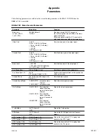
2-1. Description of Internal Switches and Indicator
2-1-1. DEC-133 Board
Switches
n
Do not change the setting of the switches described as “Factory use only”.
Ref. No.
Address
Name
Function
Factory Setting
S1101
(J-9)
Mode select switch
Factory use only
S1201
(J-11)
SDI 27 MHz Adjust switch
Factory use only
S1301
(C-2)
232C mode select switch
Factory use only
S1302
(D-2)
Reset switch
Initializes board
_
S1303
(D-2)
Mode select switch
Factory use only
LED
Ref. No. Address
Color
Name
Function
Normal State
D1302
(D-2)
Green
CPU RUN indicator
Indicates that
Lights up
CPU runs normally.
Section 2
Service Overview
A side (Component side)
1
ON
2
3
4
ON
1
ON
2
3
4
1
ON
2
3
4
A
B
C
D
E
F
G
H
J
K
S1303
D1302
S1302
S1201
S1101
S1301
1
2
3
4
5
6
7
8
9
10
11


