
56
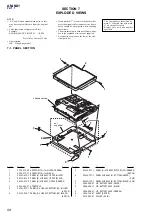
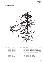
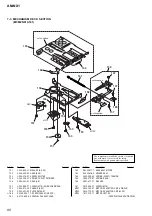
AM-NX1
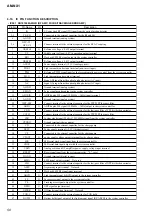
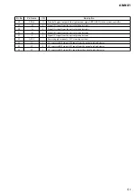
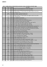
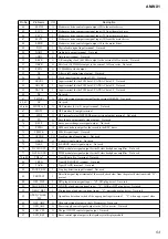
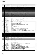
Pin No.
Pin Name
I/O
Description
190
XHP_DET
I
Headphone jack detection signal input Not used
191
SET_CODE0
I
Input terminal for the set
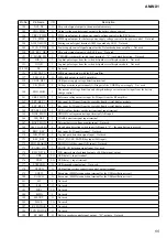
192
SET_CODE1
I
Input terminal for the set
193
SET_CODE2
I
Input terminal for the set
194
SET_CODE3
I
Input terminal for the set
195, 196
NC
O
Not used
197
VBUS5V_DET
I
Not used
198
LG_DCR_CTL
O
Not used
199
MUTE
O
Analog muting control signal output to the headphone amplifier “H”: muting ON Not used
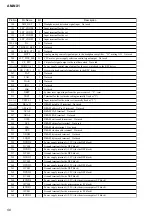
200
CLV_PWR_SEL
O
CLV motor power supply selection control signal output Not used
201
CS_RTC
O
Chip select signal output to the real time clock Not used
202 to 204
MODE1 to 3
O
Power supply control signal output for the over write head to the REC driver
205, 206
HD_CON_1, 2
O
Over write head control signal output to the REC driver
207
TAT
I
Not used
208
TAN
I
Not used
209
NAR
I
Not used
210
IDO
I
Not used
211
SAK
O
Not used
212
XRST
I
System reset signal input from the power control “L”: reset
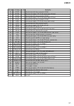
213
TRST
I
Terminal for the test mode setting (normally fixed at “L”)
214, 215
TEST0, 1
I
Input terminal for the main test (normally fixed at “L”)
216 to 231
D0 to 15
—
DRAM data0 to 15 terminal Not used
232 to 245
A00 to 13
—
DRAM address0 to 13 terminal Not used
246
XCAS
—
DRAM CAS terminal Not used
247
XRAS
—
DRAM RAS terminal Not used
248
XWE
—
DRAM write enable terminal Not used
249
XCS
—
DRAM chip select terminal Not used
250
CLK
—
DRAM clock terminal Not used
251
CKE
—
DRAM clock enable terminal Not used
252
UDQM
—
DRAM byte mask terminal Not used
253
LDQM
—
DRAM byte mask terminal Not used
254
DVDD0
—
Power supply terminal (+1.2V) (for the DSP block)
255
DVSS0
—
Ground terminal (for the DSP block)
256
DVDD1
—
Power supply terminal (+1.2V) (for the DSP block)
257
DVSS1
—
Ground terminal (for the DSP block)
258
DVDD2
—
Power supply terminal (+1.2V) (for the DSP block)
259
DVSS2
—
Ground terminal (for the DSP block)
260
DVDD3
—
Power supply terminal (+1.2V) (for the DSP block)
261
DVSS3
—
Ground terminal (for the DSP block)
262
DVDD4
—
Power supply terminal (+1.2V) (for the DSP block)
263
DVSS4
—
Ground terminal (for the DSP block)
264
IFVDD0
—
Power supply terminal (+2.2V) (for the microcomputer I/F block)
265
IFVSS0
—
Ground terminal (for the microcomputer I/F block)
266
IFVDD1
—
Power supply terminal (+2.2V) (for the microcomputer I/F block)
267
IFVSS1
—
Ground terminal (for the microcomputer I/F block)
268
IFVDD2
—
Power supply terminal (+2.2V) (for the microcomputer I/F block)
Summary of Contents for AM-NX1
Page 36: ...36 AM NX1 MEMO ...


