


47
Recording
Chapt
er
3
Rec
o
rd
ing and
P
la
y
bac
k
To record timecode after setting an initial
value (Internal Preset)
To set an initial value
1
Make the following settings in the function menu.
• Set CNTR SEL on page P1 to “TC”.
• Set TCG on page P2 to “INT”.
• Set TC MODE on page P2 to “PRESET”.
2
Press the DISPLAY button to maximize the monitor
video section.
3
Press the MENU button.
The system menu appears on the display.
4
Select “TC PRESET” using the
M
/MARK1 button or
m
/MARK2 button, then press the
,
/OUT button.
The TC PRESET MODE screen appears.
5
Use the arrow buttons and the RESET button to set the
initial timecode value.
<
/IN button or
,
/OUT button:
Select the digit to
change (it flashes).
M
/MARK1 button or
m
/MARK2 button:
Change
the value of the selected digit.
RESET button:
Reset all digits to 0.
To cancel the timecode setting
Press the MENU button.
6
Press the SET button.
The message “NOW SAVING...” appears, and the
timecode set in step
5
is displayed.
If RUN MODE on page P2 of the function menu is set
to “FREE RUN”, timecode begins to advance from the
initial value you just set.
To set timecode to the current time
1
Set RUN MODE on page P2 of the function menu to
“FREE RUN”, and set DF/NDF to “DF”.
2
Carry out steps
1
to
5
of the previous section “To
record timecode after setting an initial value (Internal
Preset)” to set the timecode to a time slightly ahead of
the current time.
3
Press the SET button at the instant when the current
time matches the displayed timecode.
To set user bits
You can record up to eight hexadecimal digits of
information (date, time, clip number, etc.) in the timecode
track.
1
Set CNTR SEL on page P1 of the function menu to
“UB”.
2
Carry out steps
2
to
4
of the previous section “To
record timecode after setting an initial value (Internal
Preset)”
.
The UB PRESET MODE screen appears.
3
Use the arrow buttons and the RESET button to set the
user bits.
<
/IN button or
,
/OUT button:
Select the digit to
change (it flashes).
M
/MARK1 button or
m
/MARK2 button:
Change
the value of the selected digit.
RESET button:
Reset all digits to 0.
Settings are made in hexadecimal (0, 1, 2,... 8, 9, A,
B,... E, F).
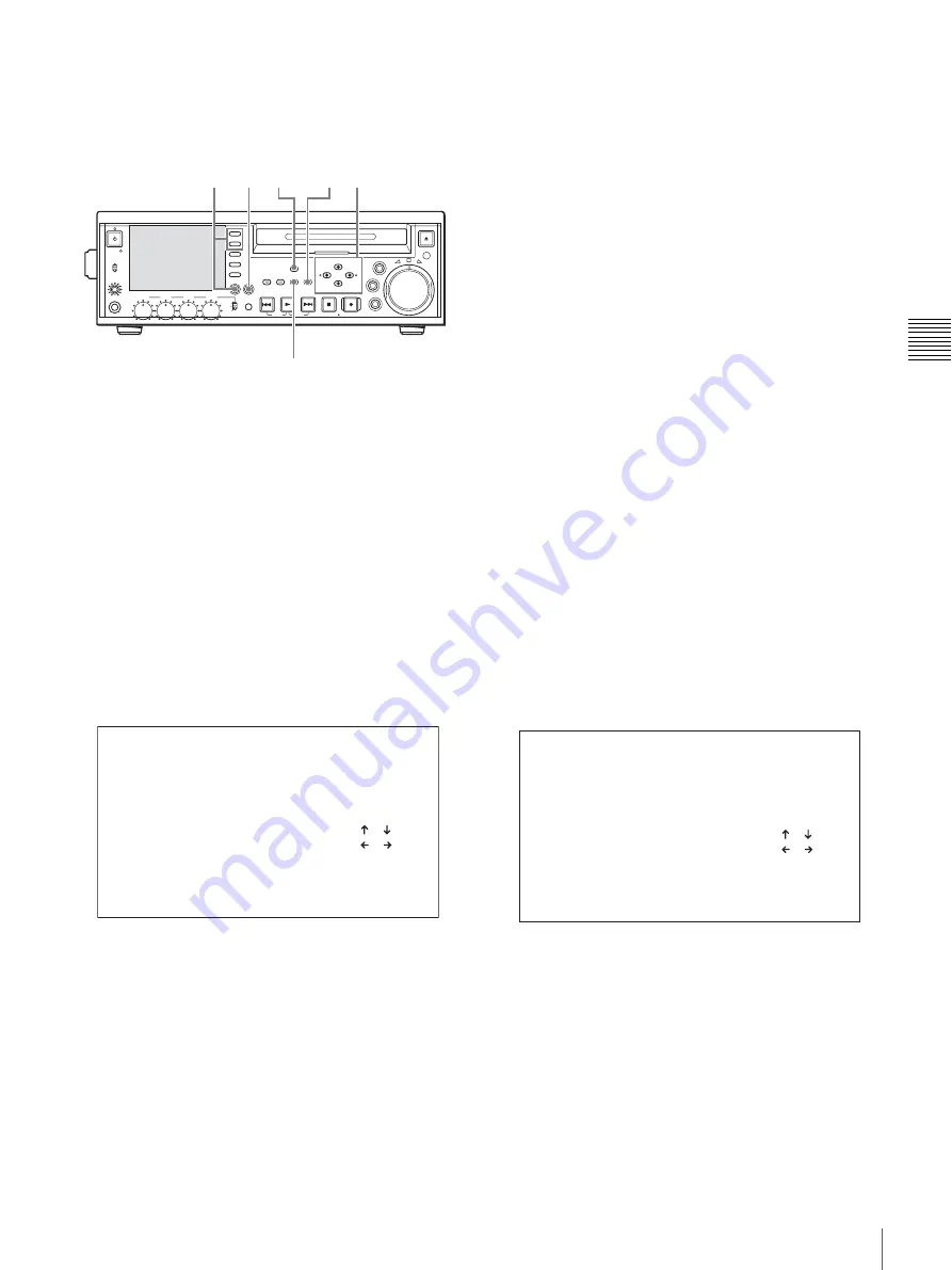
PHONES
VAR
JOG
MARK1
MENU
PAGE DISPLAY
SUB
CLIP
F1
F5
F4
F3
F2
SHIFT
CLIP
MENU
ESSENCE
MARK
SET
THUMB
NAIL
RESET
OUT
IN
MARK2
SHUTTLE
TOP
KEY INHI
EXPAND
CHAPTER
F REV
F FWD
END
PREV
NEXT
PLAY
STOP
STANDBY
REC
EJECT
CH 1
CH 2
CH 3
CH 4
NETWORK
LOCAL
REMOTE
ACCESS
LEVEL
REC
VARIABLE
PRESET
PB
2
1
6
3,5 5 4,5
TC PRESET MODE
TCG 00:00:00:00
INC/DEC : ( )( )KEY
SHIFT : ( )( )KEY
CLEAR : RESET KEY
DATA SAVE : SET KEY
ABORT : MENU KEY
UB PRESET MODE
UBG 00:00:00:00
INC/DEC : ( )( )KEY
SHIFT : ( )( )KEY
CLEAR : RESET KEY
DATA SAVE : SET KEY
ABORT : MENU KEY


