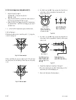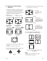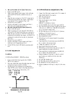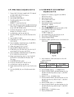
4-2
PVM-14L2/20L2
2.
Preparation of signals
The B board can process various formats of video
signal. The B board must be adjusted for each type of
video signal format respectively. Input the signals that
meet the following specifications to the connectors on
the rear panel of the unit. The component signal should
be the Sync-on-Green signal.
Signal
Signal
level
(mV)
Component
SMPTE
100 %
Y
700
Color bar B-Y
700
R-Y
700
75 %
Y
700
Color bar B-Y
525
R-Y
525
BETACAM 100 %
Y
714
SETUP 0
Color bar B-Y
1009
R-Y
1009
75 %
Y
714
Color bar B-Y
756
R-Y
756
BETACAM 100 %
Y
714
SETUP 7.5 Color bar B-Y
933
R-Y
933
75 %
Y
714
Color bar B-Y
700
R-Y
700
Composite
358NTSC
100 %
_
714
White
Burst
_
286
PAL
100 %
_
700
White
Burst
_
300
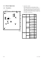
4-2. B Board Adjustments
4-2-1. Preparations
1.
Test point
TP101
TP102
TP103
TP104
TP105
TP106
TP107
TP111
TP112
TP113
TP114
TP116
TP117
TP230
TP350
TP351
TP352
TP353
TP115
A
1
2
3
4
5
B
C
D
E
A SIDE
Summary of Contents for 2500001
Page 6: ......
Page 7: ...1 1 PVM 14L2 20L2 Section 1 Service Informations 1 1 Board Locations 14 inch C X Q B B1 G H J ...
Page 14: ...1 8 PVM 14L2 20L2 1 3 Board Locations 20 inch C Q B G J H X B1 ...
Page 22: ......
Page 40: ......
Page 50: ......
Page 56: ......
Page 60: ......
Page 141: ......
Page 161: ......

